Logo

Rebuild 1972, 65 HP advice requested

Eric Wood

New member
I'm looking for advice on a 1972, 65 HP Johnson as I rebuild it this winter. Last summer, it tried to throw a connecting rod and seized. The crankcase is apart, all the internals/pistons are removed and inspected. The cylinders do NOT need to be re-bored. I will replace the crankshaft, with all new bearings except for at the wrist pins, new rings, seals, gaskets and 1 replacement piston with connecting rod attached. I have the "Clymer's" and "Intertec" (generic) repair books, but as that I do NOT fully trust them, I have STOPPED work and will wait for arrival of the actual Johnson shop manual.

Questions:
(1) For motor break-in after rebuild, Clymer's (Intertec is silent) requires a 10 hour run at half throttle (2500 rpm), in a test barrel, with a "test-weight propeller" (whatever that is). The duration seems excessive to me, and not varying the rpm does not make sense. And I would imagine to change the fuel mix when breaking it in (from 50:1 to heavier, 25:1?) is probably a good idea, but no guidance...

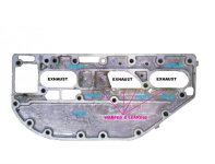
(2) The exhaust plate is NOT off the power-head, as it has 6 (out of 19) frozen bolts. Clymer's wants this plate off so that after re-assembly, I can ensure that the rings are properly seated, springy and not rotating in the grooves. The benefits of taking this plate off vs possible damage to the power head, stripped threads etc.... Is removal worth the risks?

(3) The air intake plenum to the carbs: As found was filthy, oil, dirt, seagull feathers! ....tiny bits of cowling sound-proofing foam, probably salt water spray.... Is this motor supposed to have some kind of air filter? I see no mention on my books or any on-line sources (exploded views, etc) for one. I plan on fabricating and installing an air filter after I get it running (I know it will affect the fuel mix).

(4) I have matched all the new upper (compression) piston rings, per cylinder, so that the gaps are within tolerance (0.007" to 0.017" gap). However, ALL the new lower rings seem to have a slighter looser fit (0.020" gap) when fitted. The book does not differentiate or specify a an upper vs lower ring gap tolerance. It just states "ring gap 0.007 to 0.017". Do I have the correct lower rings? (Kinda makes sense to me that the lower ring, which does not handle full compression like the upper, should be slightly looser to allow lubrication and keep the piston centered, that's its purpose... Or am I just justifying?)

(5) I plan on using Scotch pads to break the glaze on the cylinder walls and NOT a drill powered hone (I don't want to risk smearing the metal around the intake/exhaust ports ....or break the hone on the ports). Good idea? The bores are OK as is for STD rings by local machine shop check, not excessive taper, out-of-round, etc.

(6) I plan on using blue Loctite on the connecting rod bolts as that was what caused the initial failure. Good idea?

(7) Clymer's OKs and I plan on using Vasoline (NOT automotive grease) to gob all over the new bearings as I install. The gasoline/oil mix will dissolve the Vasoline as it runs. Good idea?

Thanks!
Eric, CT
 
Just use engine oil to assemble with and break in period mix the fuel 40:1 and run it at variable speeds up to 3/4 throttle. You can run WOT for short spurts but keep it below 3/4 for the first 8 hours to break in the rings. Take a large center punch and give the exhaust bolts a good smack then soak them good with PB for a few days. It is a good idea to pull the exhaust cover and make sure the water ports are clear. It is the nature of things you will likely break bolts on a older motor I prefer reverse spinning drill bits to remove broken bolts if you cant grab it with a vice grip.
 
Exhaust plate gaskets can leak water into the powerhead and it should be removed to replace the gaskets !-----Cut the heads off the stuck bolts and remove the covers.------Then deal with each bolt using a torch to get them out.----The connecting rod bolts are lubricated with engine oil and assembly is done VERY carefully so that rod caps line up.--------Loctite is not needed on those bolts !
 
Last edited:
Just use engine oil to assemble with and break in period mix the fuel 40:1 and run it at variable speeds up to 3/4 throttle. You can run WOT for short spurts but keep it below 3/4 for the first 8 hours to break in the rings. Take a large center punch and give the exhaust bolts a good smack then soak them good with PB for a few days. It is a good idea to pull the exhaust cover and make sure the water ports are clear. It is the nature of things you will likely break bolts on a older motor I prefer reverse spinning drill bits to remove broken bolts if you cant grab it with a vice grip.

40:1, got it. 10 hour total break-in run? Why should I risk damaging the power-head just to make sure the exhaust ports are clear? Is monitoring the new rings worth the risk of stripped threads?
 
Exhaust plate gaskets can leak water into the powerhead and it should be removed to replace the gaskets !-----Cut the heads off the stuck bolts and remove the covers.------Then deal with each bolt using a torch to get them out.----The connecting rod bolts are lubricated with engine oil and assembly is done VERY carefully so that rod caps line up.--------Loctite is not needed on those bolts !

Wouldn't I see evidence of past water leakage from the exhaust plates and into the power-head? Worth the risk to remove this plate so that I can monitor the new rings? Understand, no Loctite and bearing cap match marks/scratch test.
 
My comment on this is .-----------I see many folks working on their first outboard ignoring some good advice !---------If you install pistons and rings the proper way you will not break a single one.
 
Thanks, Racerone and of course I appreciate your good advice! I'm just trying to weigh the risks (rings inspection vs probable stripped threads....) I've rebuilt small 2 strokes (several chainsaws, weed wackers, leaf blowers) and one car engine (all successfully!) before, I'm no wizard for sure.... but NOT an outboard motor.... . This OTBD would be my first, Yup, I'm a virgin. I'm confident I can install the rings and pistons/rods correct. BUT.... I don't trust the Clymer's advice to remove the plate JUST to look at the installed rings.... One other thing: I plan on checking my work after one season of use (about 200 hours of engine run), open the crankcase to have a look see at the internals, hopefully without disturbing the crankshaft and rods/pistons. And if compression test after the season suggests, I will remove the head to inspect the bores.
 
The motor is 40 some years old and those gaskets need to be replaced !-------No dust out on the lakes , no filter needed.----Some folks say that these after market manuals are best used to wipe up " doggie doo " or used to start up the fireplace !
 
Also the exhaust ports may be stuffed up with carbon buildup or the inner cover damaged. Use a fine hone to deglaze the cylinders and get the proper crosshatch to break in the rings, measure the skirts on the pistons. Just because the rings fit good your crankcase precharge is created with the piston skirts. I will not rebuild a motor that needs rebuilt before you fire it off!
 
The book calls for .0035 to .0055 max piston clearance to cylinder walls. One of those 1/4 inch drive cordless impact wrench works good for breaking loose frozen bolts. Heat the bolt head and covers with a torch first just dont burn the paint!
 
Last edited:
(1) Since this is not a rebuild but a refresh all you need to do is seat the rings. You can do a full break-in in less than a hour(this is how factory breaks em in)by break-in it in on the trailer backed into lake. Simply just start and put in gear. Raise the RPM 500-600 every 5 mins till you reach 3000 rpm. Remove frome trailer and plane off and reduce RPM to 3500 and repeat the above till you reach 5000 rpm as this is max RPM for that engine.
(2) Remove the plate and replace the gaskets.Check the plate for warpage and holes being a salt motor.Do it right once!!!
(3) No filter
(4) Need to mike cylinders as sounds like their tapered or past wear limit(3.003) This would result in the wider gap.
(5) Need to use a rigid hone and recheck cylinder measurements and have machinist recheck..
(6) NO!....Most likely rod failed due to excessive RPM. Anything about 5500rpm is risky on these engines do to the small I beam rod and make sure rods match ! Do not mix Ibeams with A frame rods!!!
(7) Yes but let it idle till engine reaches temp....
Here are specs:
Factory manual specs:
piston ring gap............................... .007 min-.017 max
piston ring groove.......................... .0040 max-.0015 min
piston and wrist pin.....(loose end)... .0005-max-.0000 min
cylinder to piston........................... .0035-.0050
crank top journal........................... 1.4979-1.4974 in
crank center................................. 1.3752-1.3748 in
crank bottom................................ 1.1828-1.1823 in
crank end play.............................. .0165 max-.0006 min
 
Last edited:
I just want to thank every contributor again for their input and advice! faztbullet wrote "....(4) Need to mike cylinders as sounds like their tapered or past wear limit(3.003) This would result in the wider gap." I already had a machine shop measure the bores for taper and they were OK.

I need to clarify what I am trying to convey about the new rings and their measured gaps.

I have new rings to install in acceptable bores (3 ring sets for the 3 cylinders, each set has a top or compression ring, and a lower ring, which I am not sure what it does or is called). To measure the ring gaps, I inserted the COMPRESSION ring into each bore, concentric and centered by pushing in with a loose piston, and take the gap at the top, 1" down and 2 1/2" down into the bore (the stroke is about 2 1/2"). I then read a compression ring end gap for all 3 cylinders that stays within tolerance (above) from top to bottom of the bore. When I repeat this reading using the LOWER ring, the gap is excessive from top to bottom, all 3 new LOWER rings, for all 3 cylinders.

It appears that the lower piston ring is supposed to have a larger gap than the compression ring, by about 0.005". OR.... I have the incorrect lower rings?
 
Fatzbullet: Now THAT break-in scheme makes sense to me, at 40:1 mix, for an hour or two. And thanks for the specs. I have stopped all work until I get the Ebay shop manual I bought (the Clymers and Intertec manuals are too vague).
 
I then read a compression ring end gap for all 3 cylinders that stays within tolerance (above) from top to bottom of the bore.
And what is the ring gap reading???
When I repeat this reading using the LOWER ring, the gap is excessive from top to bottom, all 3 new LOWER rings, for all 3 cylinders.
And what is this reading???
If its .022 the cylinders are worn and needs boring. Usually ring gaps on fresh bore and new ring are in the .008-.0012. What do your cylinders mike to??? If it over 3.004 it needs bored...
 
Last edited:
Compression ring's end gap, 0.013" all 3 cylinders. Top to bottom of bore, same gap.
Bottom ring's end gap, 0.020" all 3 cylinders. Top to bottom of bore, same gap.

Did I get a bum set of rings from MarineEnginedotcom? Mixed up?
 
Sounds like it, manual states on page 5-9 "Discard and replace with new ring if gap is excessive" as upper an lower rings should be within a couple thousand's of each other...
 
The #1 failure cause on that 65hp motor is a warped exhaust cover inner plate. It is real thin and unsupported in the area of the exhaust ports, which allows it to warp. When that happens, the gasket leaks and squirts water into the cylinders, which in turn results in total powerhead destruction. I would suggest the plate be closely inspected for that reason. But be aware that even new/unwarped plate is no guarantee it won't happen in the future. Tons of those motors failed when brand new and under warranty. Even the slightest hint of overheating, such as running through weedy waters, will cause it to warp.
 

Attachments

  • 3 CYLINDER EXHAUST PLATE..jpg
    3 CYLINDER EXHAUST PLATE..jpg
    43.4 KB · Views: 102
There IS OTHER EVIDENCE that it this motor had over heated, previous owner, 10 years ago, scorched paint and wires, opposite starter side.
 
Yes, the exhaust plate appears to leak.

I'm retired so I can do science experiments! I blocked off the bottom of the power-head with 1" thick smooth plywood test plate and gasket I made, then installed cylinder head with old head gasket, pressurized to 25# of air into the cooling water water side through pipe in test plate. Saw bubbling with soapy water, at exhaust ports in bores (and can hear the leak). I will grind off the heads of the 6 frozen bolts and remove the exhaust plates and then soak and vice grip the bolts out. Have to go buy some cut-off wheels. The frozen bolts will not budge no matter what, several overnight Kroil soaks, wacked 'em several times with center punch, heated by torch, manual (hammer) impact driver all tried: no effect! Martha Focker!
 
Thanks, taking a break now, ground off the 6 bolt heads, the top (thin cover) is off, the 1" thick middle cast piece is stuck and fighting me all the way. Time to torch up the holes around the frozen bolts in the cast piece.

Did you see my question about my new piston rings and their gaps, previous?
 
Exhaust plates are removed. Ground off bolt's heads (6), removed top plate. Soaked stuck bolts in Kroil over night: No effect. Soaked aluminum corrosion around frozen bolts with solution of sodium hydroxide (lye) and picked at it with a with tweaker screwdriver till about half the depth of corrosion was gone. Heated plate by direct contact to top of woodstove to about 200F for several hours as I watched the Pats lose. (Note: Propane torch doesn't do diddly). Removed bolts with vice grips. Removed 1" thick middle plate, bottom/block side plate came off easily. Will check all 3 plates flat on a sheet of glass.
 
Last edited:
All 3 plates repaired by being sanded flat (80 grit sandpaper glued to plywood), and nicks/cuts/shallows repaired with JB Weld. 1/2" thick head-side plate AF: Not making full contact to power head, built up with JB and sanded: now makes full contact, both sides. 1" middle casting: slightly warped, now plane, both sides. Outer 1/4" plate: Slight warp, now plane. Chased bolt holes with tap, lotsa cooked gasket had oozed in.
 
Yup. These are the spots on the 1/2" thick inner or head side exhaust plate that were not making full contact, as found and over-heating caused small exhaust to water cooling leaks. Plate: Not bad enough to replace. Power head side gasket had melted to power head and inner plate. Repair on this plate----Both sides of the plate built up with JB Weld for nicks/scratches/shallows as needed and sanded plane until 100% contact. Plate will also be filed down as needed so that exhaust outlets have a smooth transition (no lips to catch the exhaust stream to cause localized overheating spots). For the plate's mating area around exhaust outlets: Will use high temperature RTV sealant (sold for wood stove flues, good up to 2000F) to also help smooth mating edges.
 
Back
Top