Logo

Random loss of power to dash

BomoFormula

New member
1994 Formula 252ss. Mercruiser 7.4l bravo 3 tb4

This intermittent issue has been plaguing me for almost 3 seasons. It’s taken most of the relaxation out of my boating. I’m getting desperate.
Here's the problem:

The boat starts/runs/idles normally. There’s a “random” stalling issue. It will stall at idle, under light throttle, at heavy throttle. It will randomly stall when hot or cold. I cannot get it to stall at will or regularly. It's not a fuel issue.
When it stalls there is no sputtering, it’s as though someone just cut the power. There are no blown fuses to or breakers tripped. It’s gone days or weeks without issue, only to return and stall multiple times a day.
The dash instruments all go dead, but every accessory still has power, (radio, blowers etc). Within 15-60seconds power returns to the dash and the motor will crank and fire up as normal. It may stall out shortly thereafter or not at all.

I replaced the eta ignition breaker last year. This seemed to fix the problem for several weeks, but then it returned.
I bypassed the kill switch, it made no difference
I disconnected the tach, no difference
I cleaned all the grounds and it seemed to work for a few weeks, and then it started stalling again.
I replaced the ignition switch, no change. Still stalling.
Jiggling wires or throttle makes no difference when running
Plug wires, coil, sensor in distributor, cap/rotor, and battery, have all been replaced.

I had had it at the shop, and they cleaned the banana plug connections and also jiggled everything but couldn’t get the boat to stall.

I figure it’s something in the ignition circuit, but I’m at a loss.
Could it be the ignition control module? The 50amp breaker at the starter going bad? Breaker on the engine? Voltage regulator going bad?
What would cause a loss of power to the dash, not trip breakers, and then disappear.
I just put her in the water today and I’ve got to solve this.
Thank you. 👍

 
My suggestion would be is to be prepared for when it happens again,

Get a test light or volt meter and keep it in the boat.

When this issue occurs, leave the key in the ON/RUN position and start testing for voltage.

Understanding how the voltage flows is the first thing.

So, all accessories are supplied by 12+ from the battery thru a wire harness to the dash. Typically the same 12+ also supplies the key switch. May be the same wire or a separate wire but one or both are typically a 10 ga red wire. This could come from the battery directly or off the main terminal on the starter where several large battery positive connections are.

Also there may be a large 90 amp (square looking) fuse at the starter. Is is not uncommon for "paint creep" to occur at this connection. Look closely at this. This paint creep can give a loss of power intermittently. This is where the 90 amp connects to the starter and where the feed wire connects to the 90 amp fuse. (to test would be to remove temporarily and connect wire direct to starter)

Because the accessories continue to function then the issue should be focused on the 12+ to the key switch.
This is where the gauges get their power from.

When this issue occurs you need to start at the Key switch and find the red wire and check for voltage if using a meter or a bright light if using a test light (test the test light across battery first to understand what a bright light looks like).

If no power at 12+ at key switch then you need to work you way back in the wire harness to determine where the loss of the 12+ is occurring.

My assumption is there is at least one, maybe two large multi pin connectors in the wire harness so both sides of the connector(s) need to be checked as you work your way back towards engine.

Thats all I have for now. got to go
 
yeh on a mid 90s boat all the engine control and monitor is via the 9-pin connector to the ign switch. The harness includes a power supply (red) wire and a black negative lead. So the circuit runs all the way to the helm and back to the engine. Typically this negative lead attaches to the engine block somewhere on the rear of the engine flywheel cover bolts. This is a prime location for corrosion and is rarely tended to due to its location. Check for rust or crud on this attachment point and clean and retighten as needed. Also check the negative lead from block to battery.
Heat, vibration, etc will make the wires move enough to break the flow of electrons, leaving you dead in the water scratching your head. Eliminate the obvious first then start looking for unicorns.
And please if you have not normalized the kill switch, do so.
One side note. These wire harnesses were not always made from marine-grade tinned wire. It's possible that it's just plain old no good and you need a new harness due to corrosion up inside the wire.
 
Thanks for all the advice.
I went through all the grounds last year. Cleaning them, the contact points, and even splitting the shielding to look for corrosion. Cleaned all connections at the perko switch. Basically inspected every connection visible. The main harness runs through the Boat and I can't visually inspect that.
The loss of power does not seem to be motion induced; that is, I've jiggled everything to no result, the Boat has gone through a lot of chop without issue, and doesn't appear to stall out after any specific big hit/motion. It's stalled at the dock idling in calm water.

If if I could get it to fail regularly or for an extended period of time I'd put a meter on it, but the power loss is usually 1 second to 1 minute. By the time I started raising the engine hatch the fault would be gone.

I get that it may be a bad connection/ground. What I don't get is why, when it loses power, it will have a "cooling off" period where there's nothing at the dash and then eventually come back. Is the short overheating something that needs time to cycle back on. I would expect a short to kill the power and stay off, to come back immediately, or to trip one of the many breakers. Any clues on this ? Maybe it'll help me pinpoint where to look.
 
First off it would not be a short but rather an OPEN. A short would cause excess current draw and possibly a spark or flame. Definitely a lot of heat.
Speaking of which, maybe a fuse is weak, maybe it has seen better days. Have you physically looked at each fuse and made sure they were in very good condition?

If you have breakers, Bypass the one (s) supplying 12+ to the key switch. Possibly the breaker could be getting hot and opening. Just a shot in the dark but what the hell..........

As suggested disconnect the PERKO and see if that helps. connect the correct wires with good nuts and bolts and a lot of elec tape for testing. Record and mark wires for reassembly before disassembly.

Does the large black connector (main engine wire harness at engine) have a hose clamp on it?

Did you inspect the 90 amp fuse for paint creep? That was not a joke it is a real condition that exists. Heat causes the paint to creep into the connection and can create an OPEN circuit.

Does your dash have any computer boards (PCB'S) attached and do you know what they are for? My cobalt does.

If it happens and you are lucky enough maybe see what the volt meter on the dash is showing??

All I got for now.........This can be a difficult issue to solve especially from a keyboard..........
 
Last edited:
Hmmmm, I never considered the perko switch to be bad. It looks clean and original, but bypassing is pretty easy.

I noticed the voltmeter on dash is showing a tick under 13v. I’m planning on testing the alternator and connections for charging/voltage drops as soon as it stops raining. Alternator also looks original.

No PCbs under the dash.

I replaced the ignition breaker last year

There is a hose clamp on the banana plug

I’ll also be checking the 90amp fuse for paint creep. I do know the starter was replaced several times before I bought the boat. The most recent was about 5 years ago.

Thank you. This gives me a few places to look into that I hadn’t before.
 
A fully charged battery is at ~ 12.8 volts

At about 1500-2000 rpm voltage should be 13.5-14.5 normally.
You may want to also load test battery.
Not that it is your issue.
Duoble check Alt output at battery and compare to volt metter in dash to be sure...
Not uncommon for an aging volt meeter to read a little lower than battery voltage.
 
FYI, the Perko MBSSs are known to have light contacts and weak contact spring pressure. I have physically broken these apart as to compare them to other brands.
BlueSea and Cole Hersee are much better units, IMO!

I will agree that it would be unlikely that the Perko contacts would loose continuity and then mysteriously re-gain continuity shortly afterwards.

Have you pulled the main hull harness and engine harness connector apart (the one you called a banana plug) to inspect the contacts?


.
 
I ordered a new 90a fuse, because it's cheap and I thought I'd just swap it out. When I got down to the starter there was no fuse there. The 3 wires were just directly attached.
IMG_3639.jpg

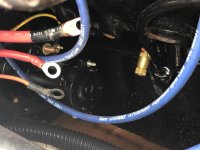
I cleaned up the 4 connectors, and reattached.

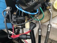
I did find what looks exactly like a 90a fuse attached to a bracket with the trim pump. There's no markings, is it the same as the one I just bought? Is this fuse just a relocated version of the one that's supposed to be on the starter? It was a bit corroded so cleaned it up.


IMG_3640.jpg

I cleaned up those connections, and also found a fuse. It was a little stuck, and when I opened it the glass was cracked. I'm not sure if it was from me, or it was cracked before. It's 32v, and intact, other than the broken glass.
IMG_3641.jpg
 
Last edited:
Today I let the engine run for 20min till it cut out, then restarted. It cut out sooner, restarted...etc. eventually however, power didn’t return quickly, it took 10 min. The next time it didn’t come back at all. Perfect, now It’s really broken and I can put a meter to it.
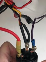
I started at the ignition switch.

4E38EC47-9A59-4D8B-8784-97A9B8FAA60C.jpg

No power at the purple wire, (from kill switch) terminal I
Power at the B terminal
No power at the S terminal
I believe the cut off wire is from a halon system... which doesn’t seem to exist as far as I can tell

Then I went back to the slave solenoid.

CD189772-7C57-478B-AF25-09F976A37FD3.jpg
No power on C
Power on A
No power on B
Connecting A&D gives power, so ground is good
Jumping A&B does crank engine
tested the connection from switch wire to solenoid and it’s connected.

I bypassed the kill switch yesterday when she was still starting and the engine continued to die. I ruled that out.

Could it it be the neutral safety switch? Jiggling the handle never appeared to cause stalling, or bringing back power.
this is my throttle/shifter. Any clues on how to get in there and test the switch?

D5242A98-4DB4-4A33-A644-6D2E6843CBA8.jpg

Am I overlooking something?
 
Key switch,

Red is battery +

yellow with red stripe is Crank which goes through neutral safety switch in shifter.

Purple is Ignition on when key is in run position

What is second wire on terminal with yellow with red stripe?

Slave solenoid,

Red Battery + (A) This wire comes from Large terminal at starter (main battery + connection with multiple wires)

Large yellow with red stripe goes to starter solenoid (crank) (B)

Small yellow with red stripe is from neutral safety switch (key switch to neutral safety to slave) (C)

Black ground (D)

Small wires activate slave solenoid coil which now transfers power from A to B to starter solenoid.


What is not happening? No crank or no start?

No crank would be loss of power thru yellow with red stripe, either from key switch, neutral safety or slave or starter solenoid.

No start would be purple wire which feeds back to ignition coil. This is a bit more involved. (you bypassed lanyard (kill)?

Next would be large black connector at engine wire harness, next would be coil, Remove Tachometer lead (grey) at coil - and see if it starts. Bad tach can take down ignition.


Jumping small yellow (C) to large red (A) should activate slave solenoid causing engine to crank over (only), Bypassing ignition switch. This will bypass dash and main wire harness connector for cranking test only.

To test ignition while bypassing dash and engine wire harness, run a jumper from (A) to ignition coil + then jump (C) to (A) engine should start.

(remember if doing this the only way to shut off engine is to disconnect wire from coil so you may want to install a on/off switch in jumper wire going to coil + so you can kill power easily). I would also recommend installing a momentary on/off switch in jumper used to activate slave solenoid.)
This way you would turn on switch to coil + and then turn on (momentarily) the slave activation (crank) until engine starts then it would release so no more power to slave solenoid.

In other words you are manually being the ignition switch but at the engine not the dash.
this bypasses all wires except Tach lead. So try that first. disconnect grey wire at coil - or at tach in dash and try to start normally. If that fails then try all of the above.


Hope this helps...........let us know.
 
Last edited:
Whether Merc, OMC, Volvo Penta or other........ Yellow w/ Red stripe is typically used for the S circuit.
S = starter motor solenoid.

If your start system incorporates a "slave" solenoid, the slave simply serves as a means of preventing voltage loss (to the starter motor solenoid) during cranking.

Merc starter motor circuit example.jpg
 
Whether Merc, OMC, Volvo Penta or other........ Yellow w/ Red stripe is typically used for the S circuit.
S = starter motor solenoid.

If your start system incorporates a "slave" solenoid, the slave simply serves as a means of preventing voltage loss (to the starter motor solenoid) during cranking.

View attachment 20589

Moron

ALL MERCRUISER I/O products with the exception of old style 170/470 with ford type (no starter mounted solenoid) have a slave solenoid............

Again a stupid, wasted useless post due to a lack of product knowledge..................ugh
 
There is no cranking or starting or power to the instruments at the dash. Kill switch is bypassed.

I tried a different switch switch that I know works. Nothing.
In run or start at the key there is no power at the s or I wire.
I connected the B&I wires directly and jumpered the S wire, (Hotwire) Nothing.
I removed grey wire at coil, nothing.
There is 12.6v at the B wire at the helm.

I bypassed the helm as you suggested, and made the connections between coil&slave solenoid and she fired right up. I only let it run a minute.

So I know the engine works.

Where should I be looking to figure out why both the purple I wire and red yellow S wire don't work?
 
If the connector is fine, and you have +12VDC at the Big RED wire, at the IGN SW, then a bad connection is still possible.

I read where you bypassed the harness so deemed the engine good.

when you removed the wires at the IGN switch and connect BAT to IGN, hook a voltmeter to that connection - note the value, and then - while watching the meter, jumper the S wire and note that reading.....
 
Is there a hose clamp on large black connector?

If not you should install one.

when tightened it maintains pin to socket contact.
 
Breaker hasn’t been tripped. 12+v at both terminals.
Im going out to take a close look at the wire from engine side harness back, as well as the connection for pin 6.
 
I've seen a couple factory harnesses with defects.....not common by any means....and they were a royal pain to locate the fault......

If you are checking with a digital voltmeter (ie both sides of the breaker) you may want to use an old fashioned, light bulb-based test light....something that needs at least a full AMP of current to indicate 'good'. your stuff is 25 years old so corrosion is quite likely (though it may be hidden). a DVM doesn't use enough current to show a corroded wire or connector.....
 
Really cleaned the crap out of all the pins. Now I get 12+v at pin 6.
Still no response from instrument panel with the key on, and no cranking when turned to run.
 
The pins are split pin,
You can spread them a small amount if needed.

I am not at pc so i can review schematic but will in the morning.

There is a very good chance that all wires from connector go thru another multi pin connector behind dash.

The 10 guage RED wrie from black engine connector should be easy to follow.

Do you have 12 v at red wire on kwy switch?
 
Yes 12v at b terminal at switch

Key off
12+v at B
.035v at S
0v at I


Key "run"
Fluctuating voltage at B. .035v-.4v
.005v at S
.013v at I


Key "start"
Same fluctuating voltage at B
.008v at I
Fluctuating voltage at S .03-.4v
 
Disconnect black connector and redo test.

Isolate engine From dash..

i dont like volt meters in these situations i like a test light.

But do the disconnect test to isolate
 
Disconnect black connector and redo test.

Isolate engine From dash..

i dont like volt meters in these situations i like a test light.

But do the disconnect test to isolate

OOOOPS.....it was getting late...........


Looked at schematics,
Pin 6 is 12 volts to dash...

As I mentioned. Using a volt meter is not always best in these situations.


You never answered my question on the second wire on the key switch terminal at the ywllow with red stripe connection.

It looks black and if so that would be ground.

Please respond with that, disconnect if you are unsure and retry to start.

If still no go then you have a bad connection from black connector to dash somewhere.
 
You never answered my question on the second wire on the key switch terminal at the ywllow with red stripe connection.

It looks black and if so that would be ground

Sorry. That 2nd black wire is for a halon system indicator light. I believe someone disabled/removed the system. The light has never worked. I disconnected it the day after you asked me what it was.

Should I try running a jumper wire from the engine side harness to the I terminal on the ignition switch? And then the same for the yellow/red on the S terminal? Just to see if my issue lies somewhere in harness from the helm to the engine?
 
Back
Top