Logo

no spark at all on one engine , related to timing shunt (454 crusader)

realcaptron

Regular Contributor
Friends, I have encountered a new problem with my recently installed delco est's. Last week, I was fine tuning the carb adjustments at idle and when done with that, I decided to check once more the base timing and total advance for the heck of it.
I have timed these engines several times since installing a couple months ago and following the same procedure, this is what happened.....engine idling, hook up timing light, insert timing shunt into the distributor, connect shunt lead to battery positive....as soon as I touched the battery, the engine died AND I HAVE HAD NO IGNITION SINCE!. I have read the choke leads and the ignition coil with the ignition switch in "on" position (buzzer going off) and there is NO voltage at all to coil or choke....obviously I don't have any spark to start the motor. It just cranks.

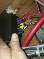
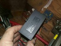
So....please guide me..what happened? This is an old boat 1976 Crusader with old technology. There is an engine wiring harness but no reset or any other fuse or transistors that I can find. I don't understand why ignition switch is sending signal to buzzer and to starter solenoid but nothing to coil or choke positives.
On guy mentioned that some of the older harnesses had internal resistors that he thinks may have fried. I am asking your opinions and also what do you think would happen if I bypassed the 12v return wire from ignition straight to the coil and choke leads? If I am thereby supplying 12v to the coil yet still using the ignition key for cranking, would I damage anything or would it be ok to do this? Reason I want to do that is simply to verify that the engine itself will start and run, then go back to tracing the root cause.
I did swap the coil and ignition module from non running engine to running engine and no change. The running engine still starts and the non running one did not, so I am ruling out coil or module. Help please!
 
Assuming you removed the ballast resistor, I'd suspect the connection there.

the ignition switch appears to be functioning correctly - the path to the buzzer and the coil are separate, but fed from the RUN terminal of the key so something went wrong (opened) between the RUN terminal and the coil/choke connection. The cranking circuit is another separate path from the key.

If you want to 'jump' the coil directly to the battery (bypassing the key) for test purposes ONLY, I'd suggest using a fused jumper as you don't know what else is going on in the existing wiring....otherwise, I'd be inclined to remove the wires to the key switch. Just realize what's going on and what needs to happen to shut the engine off.

Swapping electronic parts without the required power source is a time waster (unless you have a retainer account that needs depletion).....

Mark...Where is the ballast resistor? You have helped me greatly with this boat and you sent me your copy of the crusader manual. Looking it over, I see that all crusaders had a reset breaker, but I can't find one on this boat. Looks like just a harness between engine and helm. Could the ignition switch itself have been damaged by a short or overload when I connected shunt to positive? Btw...the buzzer has now stopped working as well, but engine still cranks and gages still activate with switch in the on position
 
old school stuff:

coils that need a ballast have about a 1.5 Ohm primary. They want to run on 10V.
coils that need no ballast are closer to 3 Ohm. They want to see the full 12V.

So, that might be the first step. What coil do you have?
I'm not quite old enough to have worked on a wire harness with integral R, but I have heard of such things. My 440 Mopar was the only thing I had with a ballast R.
My 1990 Crusader gen IV parts book shows no ballast, but does have both the early EST and Prestolite distributors.
Yours had/has points??

Dave..I'm under the bridge on this thing now trying to trace the ignition wiring. I found a peculiar plastic black box that I am trying to figure out wjatvit is. I will send a pic when I get home. It appears that ignition wires are running into it and it looks like wires come out of it to the engine. It has 8 terminals on it, 2 of which go to starboard ignition switch( the one in question). It has floscan on one side of it and "motometer" on the other. This boat does not have floscan gages and I don't think it ever did, so trying to find out if that is some sort of circuit protection.
 
ballast resistor should have been removed when the EST kits went in....

do you have +12VDC at the RUN terminal of the key switch, with the key on? if yes, and there is NOT +12VDC at the COIL, with the key on, there's a break in the wire between the two. you can either find the break and correct it or you could just run a new (purple) wire.
 
can you reword this one so its not ambiguous?


or maybe the pic will clear things up...

Not sure what you mean Mark. Up under the flybridge I found a black box with wires connecting to at least the starboard ignition. Reminder ....This is brand new Delco est distributor with coil that came with it. Boat was running. I had timed it several times with the new Delco est. I was trying to find tune it when something blew as I connected timing shunt to positive. There is 12v to buzzer and gages but nothing back down to engine ignition coil or choke, and it cranks so starter terminal is energizing.
 
Not sure what you mean Mark. Up under the flybridge I found a black box with wires connecting to at least the starboard ignition. Reminder ....This is brand new Delco est distributor with coil that came with it. Boat was running. I had timed it several times with the new Delco est. I was trying to find tune it when something blew as I connected timing shunt to positive. There is 12v to buzzer and gages but nothing back down to engine ignition coil or choke, and it cranks so starter terminal is energizing.

LIke MM said; clearly there is an open on the IGN side of things. Installs SHOULD have a fuse or breaker somewhere. Usually the engine, but on an old system, I've even seen dash fuses inline with the IGN. I've also seen bad connections on the engine wire harness, like a 9 pole trailer connector type of deal. The IG switch has raw +12 coming in and switched STarter and IGNition coming out. So, you know the 12V made it to the ig switch OK. DMM can solve this, might need long leads...
 
LIke MM said; clearly there is an open on the IGN side of things. Installs SHOULD have a fuse or breaker somewhere. Usually the engine, but on an old system, I've even seen dash fuses inline with the IGN. I've also seen bad connections on the engine wire harness, like a 9 pole trailer connector type of deal. The IG switch has raw +12 coming in and switched STarter and IGNition coming out. So, you know the 12V made it to the ig switch OK. DMM can solve this, might need long leads...

Dave, this boat had HEI electronic Distributors on it when I bought it but they were automotive and I switch them out to the Delco Marine EST distributors. To be honest I don't know what a ballast resistor looks like or where it would have been mounted if it was on the boat when the itchy eyes were on all that I can find is a harness that goes from engine to the helm and it looks like a trailer wire connector with about eight pens rectangular
 
Ron - the ambiguity, to me, was the "it has flowscan on one side"....my analog displace (ancient) flowscan has a converter box.....

Its likely the ballast resistors went when the old HEIs went in....I'd guess the open is where the ballast resistor was....they are rectangular in shape, maybe 1/2" square and 2-3" long, with the leads coming out axially - one on each end.

If the harness(es) between the switch and the engine are original, I'd think running a new wire would be best as you don't know what condition the existing wire is. If you do that, I'd suggest leaving a loop (12" diameter) at the main connector, if one is used.

Mark ( and Dave) you guys are awesome and have both been helping me a lot with this boat for several months. I'm gonna try to upload a picture of the mysterious floscan box under the bridge.
I'm done for the day on it but back on it tomorrow. Currently my plan is to verify I have 12v at the wire lead that should be going back down to engine from the switch. It is on the same switch pole as the buzzer and gages but is a separate wire going in its own direction. If that is there, then verify or not that 12v is making its way back down from bridge to the harness at control side. If it is, then possibly jump over the harness on that wire only to the purple wire that supplies coil and choke.....Mark if I run a totally new wire, what do you mean leave a 12" loop?
 
...and it looks like a trailer wire connector with about eight pens rectangular

I've had issues with these on my motors. Fairly simple job to unplug and see if there is any brass corrosion on either side. Leading to the use of tiny bits of sandpaper, tiny wire brushes, and topped off with a light smashing of the female end and some silcone grease. :cool:
Nothing I would want to fly with, but...

12": MM wants you to have some excess at the connector. In case it gets made into a new connector.
 
Mark and Dave, trying to upload a pic of that odd black plastic box that says floscan on it. Honestly, there is zero evidence that this boat ever had flow meters in the fuel lines and no holes on the dash for gages, so I'm not sure what this is for...but it does have wires going to the ignition switch on starboard (the side in question). I'm trying to trace and see if anything is going to the port side ignition tomorrow.
 
Can someone tell me how to upload a pic here? I have tried a couple methods and not working. I am clicking on insert file, selecting my image and selecting upload, yet nothing shows up?
 
there's a link to the how to in the help section....going from memory, the only trick is to save the pic in a 'compact' format.

you then click the go advance reply buttton, click manage attachments, upload the pic, then paste a link to the selected photo in the text box of the reply box.

if you wa, I can send you my email via PM, and I can post it for the near term....

PS - the replacement ballast resistors i looked at last night have tabs @ 90 degrees to the main axis....either QC tabs or rings, for a thru bolt...

Yes Mark..I will check my pm for your email. I think I may have your email already but please resend. I will send you the pics
 
hopefully Ron's pic's attached and are visible....
 

Attachments

  • ron - two.jpg
    ron - two.jpg
    63.5 KB · Views: 31
  • ron -one.jpg
    ron -one.jpg
    54.5 KB · Views: 32
looks like some kind of sensor translator....maybe an additional alarm box. two issues i see: 1) I'd bet the wire colors used to connect the thing were not selected per the industry standard and 2) the crimp connectors and the tool used really aren't marine friendly or compatible.....

Looks like there are some ID markings at the male spades on the box...if they are in German, I doubt I could help further.....if in english, a list of what they are as well as what each is connected to (like Wire #1- STBD oil Pressure gauge, SENDER terminal) may help.

You can remove the wire that goes to the ignition switch's RUN terminal and tape it off for trouble shooting.....

I took the day off from the boat to do some honey-dos, but back there tomorrow. Sensor translator is interesting observation. The buzzers on the boat alarm when key is switched on prior to starter, and I believe they are tied to gages as alarms for overtemp, low oil pressure and such. I'm guessing you don't think it is related to the no spark issue I have. I keep going back to the notion of internal resistors in that wire harness. IF we thought that the harness might be the break, could I not just cut the harness out and direct connect each wire to its mate? Why do you want current resistance in the runs anyway?
 
IF the box is a warning system driven from the gauges' sensors, I doubt most of its failure modes would inhibit the ignition....pulll the wire between the RUN terminal and the box, tape it up and turn the key on...if you have +12VDC at the coil, you MAY have resolved the issue....do you hear TWO different pitches of buzzers when the key is on?

I would say it's most likely that the purple lead, from the key's IGN ternimal to the coil/choke, is open at where the original ballast resistor used to be. Another potential would be (as stated earlier) there's a fuse in that wire and it has opened. If the motometer box has failed bigtime, it could be shorting the IGN line internally - removing the connection and taping it off should resolve that...one could pull the purple lead from the coil and measure its resistance to ground...

Since the switch is up on a bridge, you could consider the poor man's "long extension lead" alternative. if you don't have a long wire with jumper clips, one way to test a long run (ie the ignition feed from the key to the coil) is to isolate the wire by disconnecting both ends. go to the far end and clip a normal jumper clip to the free end of the wire and the other end to ground....go back to the other end and measure the resistance between the wire's free end and ground - should be zero....and variation - good for modest current runs - is to go to the far end and connect a test light (with old school bulb) to the free end of the wire and ground. Go to the other end of the wire and connect it to a good +12VDC source and, if the test light is on, the wire has adequate continuity....

Well guys, the boat is running again. I want to give you a long winded summary and get your feedback if any. I FOUND A LOOSE WIRE. So after days of laying under the bridge and cutting off every ziptie and unraveling all I could to see the wires, it came down to the wire coming off the ignition "run" terminal, which on this boat did not go directly to purple, but instead went to a terminal connection which then proceeded to a disconnected engine synchronizer, then from there back to the terminal strip for starboard engine purple wire. In my case the connection at non operating synchronizor was loose. As soon as I tightened it, I had 12v at the coil. As for the mysterious floscan box, the leads there were NOT going to switch at all like I originally thought. They are running to an old mechanical 3 digit resettable counter with a 3 position switch. I'm now guessing that at one time the boat did have an archaic fuel flow meter system on it and I'm betting that the counter counted gallons consumed like an odometer. If you knew how much fuel you had to begin a trip, you would be able to determine fuel remaining....but that's just a guess on my part. I also believe this boat was rewired because all of the wire under the bridge is RED up to the terminal strips for each engine, where the color coded wires from the harness mate up. I also discovered that there is ZERO circuit protection anywhere in this boat except for in line fuses for things like stereo, vhf, gps etc.
Now for your guidance....I am afraid to hook up the timing shunt again after what happened, but I'm kinda thinking that with the loose wire in there to purple, when I hooked up the shunt, it asked for a hair more current than the loose connection could tolerate and it killed the spark. So do I go back and set base timing with the shunt, or should I just check advance without the shunt and increasing rpms to ensure that I am not advancing beyond 28*???
And thank you all for your tremendous help, especially Mark and Dave who continue to put up with my dumb quetions.
 
Glad you found the issue....and understand the wiring a bit better....

I'm think it was just coincidence, that the open occurred when the timing was checked....the module going into bypass mode doesn't draw anything additional to amount to anything. I'd be inclined to check and make sure the advance max value is good....if so, you should be ok for the timing.

as far as the ALL red wires, not the best approach but should be ok assuming that a good grade of tinned wire was used along with appropriate terminations....if the ends look like the ones in the motometer pic, I'd be inclined to put more appropriate ones on and to do so using the proper tool.

I'd also suggest adding decent breakers in the not too distant future.....I've got a preference for military grade ones but that's just me...
 
Glad you found the issue....and understand the wiring a bit better....

I'm think it was just coincidence, that the open occurred when the timing was checked....the module going into bypass mode doesn't draw anything additional to amount to anything. I'd be inclined to check and make sure the advance max value is good....if so, you should be ok for the timing.

Just an update here....over the weekend I went ahead and double checked the base timing on both motors with the delco timing shunt
as far as the ALL red wires, not the best approach but should be ok assuming that a good grade of tinned wire was used along with appropriate terminations....if the ends look like the ones in the motometer pic, I'd be inclined to put more appropriate ones on and to do so using the proper tool.

I'd also suggest adding decent breakers in the not too distant future.....I've got a preference for military grade ones but that's just me...
just an update here. over the weekend I went ahead and doublechecked base timing with the delco shunt and put them both at about 8* btdc. It is worth mentioning that when I plug in the shunt on the port motor, there is no change in rpm or sound of motor, yet when I do it to starboard motor(the one that gave me fits last week) it markedly stumbles and rpms go down. When shunt is removed, rpms jump up a couple hundred rpms. Anyway, then without shunt I increased rpms to 1500, 2000, 2500, 2800.....on the port motor, it was advancing to about 33* total, so I loosened distributor and retarded it slightly to hold it at 28* max. It still idles fine and starts fine. When doing the same thing to starboard side, I'm not even getting to 20* advance total. On this motor, rather than advance the distributor to basically "force" it to advance, I just left it alone because I will be almost always operating the boat around 1500-1600 rpms anyway for fuel. When I had the electrical glitch last week with the shunt, I had forced the advance at high rpm which resulted in an idle speed advance of about 14*. I decided this time to just let it ride for a while and see how things go, because the engine(s) is/are starting up really nicely right now and run at dead idle in gear and out smooth as can be without any threat of stalling or roughness. But I welcome feedback as always.
 
just an update here. over the weekend I went ahead and doublechecked base timing with the delco shunt and put them both at about 8* btdc. It is worth mentioning that when I plug in the shunt on the port motor, there is no change in rpm or sound of motor, yet when I do it to starboard motor(the one that gave me fits last week) it markedly stumbles and rpms go down. When shunt is removed, rpms jump up a couple hundred rpms. Anyway, then without shunt I increased rpms to 1500, 2000, 2500, 2800.....on the port motor, it was advancing to about 33* total, so I loosened distributor and retarded it slightly to hold it at 28* max. It still idles fine and starts fine. When doing the same thing to starboard side, I'm not even getting to 20* advance total. On this motor, rather than advance the distributor to basically "force" it to advance, I just left it alone because I will be almost always operating the boat around 1500-1600 rpms anyway for fuel. When I had the electrical glitch last week with the shunt, I had forced the advance at high rpm which resulted in an idle speed advance of about 14*. I decided this time to just let it ride for a while and see how things go, because the engine(s) is/are starting up really nicely right now and run at dead idle in gear and out smooth as can be without any threat of stalling or roughness. But I welcome feedback as always.

hmmm. You want that 20 deg advance. I ran 10 to 30 deg for thousands of hours, mostly with marina fed hi-test, but as low as 89, never any pinging.
If you wanna feed 87 octance, then 28 is better. Still want close to 20 degrees advance though.
 
hmmm. You want that 20 deg advance. I ran 10 to 30 deg for thousands of hours, mostly with marina fed hi-test, but as low as 89, never any pinging.
If you wanna feed 87 octance, then 28 is better. Still want close to 20 degrees advance though.
Dave..what is your advice ? Should I ignore the base timing and just manually advance the distributor at say, 2500 rpm to get it to advance over 20*, and then just let idle be wherever it Is? I appreciate your contributions on my various issues.
 
Dave..what is your advice ? Should I ignore the base timing and just manually advance the distributor at say, 2500 rpm to get it to advance over 20*, and then just let idle be wherever it Is? I appreciate your contributions on my various issues.

I believe the EST uses electronics to alter the advance. That being the case, it points to a defective ignition module.
The twenty degrees I reference is the difference between 700 and 3700 rpm timing.
 
I agree with dave on the bad module....with the EST "internal to the module" control scheme, the advance starts real early (compared to a mechanical control distributor). Once the shut is disabled, the timing usually advances quite a bit. I've found the best way to set them is to dial in full advance, at the specified RPM and then not to worry about the idle value as long as the engine starts ok when hot....its not uncommon to see less than 15 degrees of total advance on an EST distributor...and there's no way to adjust it (without adding an ECU).
 
Why not swap modules between the two engines? That should prove if it is the module or not, unless they are specific to engine rotation.
 
Back
Top