I am just back from the boat after putting the engine in base timing mode again. Double checked: LED signals the Diag-Mode only as described above, no further codes. The Motor runs on 1,200 goes down on 1,000 goes up to 1,400 then back on 1,200 for about 5 sec. so seems that the sensors are not the reason why?
In normal mode disconnected TPS, no change, cannot press the throttle plates more down, they close completely.
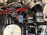
concerning the loose ground cable 2 pics enclosed. The "block" is directly behind/under the ignition coil...
1step close to order a diacom in the states - no service company with a scan tool is available short term, already in touch with rinda...
weekend i will test vacuum - is this still under suspicion?
Before answering any other questions,
Has the fuel pressure been checked? I don't remember seeing anything about it, other than post #2.
Test at Key On/Engine Off
Idle
2000RPM
WOT
Fuel pressure MUST be tested on the water, with the engine under load. Testing on the trailer or in neutral isn't a valid way to do this.
Vacuum is always important but if you find a manual, you can use a voltmeter to measure the control & return voltage on each sensor (TPA, MAP, ECT) and measure the resistance on the ECT, to make sure it's within normal range. That one won't cause the engine to hunt for the correct engine speed, though- it will make hot starting difficult if the resistance is too high or it will run too lean if it's too low.
A quick version of what happens when these systems operate, assuming you have no training on this-
When the key is turned to ON, the MAP sensor reads the barometric air pressure, even if the key goes directly to Crank- it takes a very short time to read this and it continues until the engine shuts off.
RPM- at or below 300 RPM, the engine is cranking, not running. Above 300 RPM, the ECM program acts appropriately for a running engine. The ECM is programmed to idle at about 600-700 RPM- the timing mark will jump around at idle due to the program using Spark Stabilization to ensure smooth idle. It's not for performance, it's because people like smooth idle.
The TPS tells the ECM whether the engine is idling or at higher speed when at or below 2% throttle position and during idle, it controls the engine. If it fails, the ECM defaults to a fixed 12% Throttle Position and the engine will run, but it won't be as responsive as it should be. If the throttle position reads 100%, the engine won't start or run because that is when the throttle 'is' wide open and during cranking, shutting off the fuel flow will clear a flooded engine. The TPS also delivers more fuel when the throttle opens 20% or more in a short time- this is called 'acceleration enrichment', when it closes by 20% or more in a short time, it delivers less fuel, in what's called 'deceleration enleanment'.
MAP sensor- in addition to reading barometric pressure, it acts as an electronic vacuum gauge for the ECM. Highest vacuum means the throttle is closed, lowest vacuum means it's closed. Hard acceleration (sudden drop in vacuum) will make the MAP sensor deliver more fuel and hard deceleration (sudden increase in vacuum) will cause it to deliver less fuel.
When the engine is running, the MAP sensor runs the show.
That said, MAP sensors and the rubber tube do fail, occasionally- one test for this is to disconnect the rubber tube and if idle settles down, check the tube for cracks and loose fit at either end. I have seen both. If the tube is OK, use a vacuum pump to test the MAP sensor as mentioned in pot #5- this is more easily seen with the diagnostic computer/software, but it can be done with a multimeter, too. Increase vacuum using the pump (not a lot- the sensor's diaphragm is relatively fragile):
Map sensor wire colors-
Light Green- Return signal, sent to ECM as voltage range of ~2VDC to ~5VDC
Gray- 5VDC reference voltage
Black- Ground
TPS wire colors-
Dark blue Return signal, same voltage range as MAP sensor
Gray- 5VDC reference voltage
Black- Ground


")
