Logo

Honda BF75A Stern Bracket Blocked by Shift-Shaft Spline

jackmanjls

New member
1997 Honda BF75A — Stern Bracket Removal

Problem: The stern bracket makes hard contact with the “Shift shaft spline” before it can move far enough to clear the 12 × 150 mm mounting studs, preventing the bracket from separating.

The lower unit, lower mounts, T&T connections and two upper nuts have been removed.

Can the shift shaft spline be removed or retracted without removing the powerhead?
 

Attachments

  • 150mm and SSB resize.jpg
    150mm and SSB resize.jpg
    688.2 KB · Views: 10
Hi,
I have no experience with that model so I'm definitely guessing but it looks like that shaft can be pulled out after the gearcase is removed.

Item 12 in link.


I believe #13 "stopper" just limits the spline engagement depth and doesn't hold the shafts together.

Items 14 and 11 will stay with the gearcase. It will be important to index the 3 shafts properly when going back together so, if possible, mark them. I think having the transmission in neutral before pulling the lower unit would be what's needed but, again, just guessing so that could be wrong.

Good luck.
 
Thanks. The gearcase was removed in neutral. I tried pulling the remaining shaft downward from inside the midsection. It has slight up-and-down movement, but it will not withdraw or move far enough for the upper spline to clear the stern bracket.

The labeled photo shows the upper spline making hard contact while the 150 mm mounting stud is still substantially engaged. Is this shaft normally removable downward, or is it retained at its upper end?
 
I don't think it's "secured" but I'm probably full-of-iit. All I know is that you never want to use any force until you know for sure.

I pointed out the "stopper" in the link (item 13) because, if that shaft is positively being held, it's probably there because, looking at the depiction of shift rod."A" in the link below (item 4) the snap ring (item 31) there is for holding all the stuff above it.....
...that is, I think.
Still guessing.but I'm gonna try to find out. I'll get back to you if I do.

 
jgmo...Thanks for looking into this. Here is the exact motor information:

Model: Honda BF75A
Frame/Serial number: BBAL-1002136

For clarity, this video shows the Shift Shaft B spline and the exact point where it blocks the stern bracket:

Video: SS B.mp4

The gearcase is removed, but the shaft has only slight vertical movement and will not retract far enough to clear the bracket.
 
Well, unfortunatly, I can only reiterate that I found no mention of a "mechanical attachment" for keeping that shift ROD from sliding out of the shift SHAFT splines.

I BELIEVE that the ROD should simply pull out just as the splines at the bottom disengaged when the gearcase was removed.

But...
...just as in religion, BELIEVING is not the same as KNOWING.

I just don't KNOW why that rod won't slide down and out of there because I've never pulled one out.

I'm pretty sure I have read horror stories about people causing the snap ring on the shift shaft to pop off and then having one heck of a time getting it put back on.
So, maybe that snap ring is involved in some way.

i'm very sorry I can't provide a specific answer as to what you need to do.
 
jgmo,
Thank you for taking the time to research it. Your warning about the snap ring is useful, and I won’t apply force without confirming the procedure. The rod has slight vertical movement but reaches a definite stop in both directions, so something is limiting its travel. I have also contacted an outboard salvage shop that may have the same assembly available to inspect.
 
Yeah man, I'm positive that going slow and making sure will save you some misery.

I'm looking forward to reading how you ultimately "slay this dragon" so please keep us informed about what you find.

Wish I could have been of more help with this.

Best of luck.
 
I found that the long midsection component is Boats.net item #12, “Rod A, Shift,” part 24320-ZW1-900. Item #13 is a stopper ring fitted at its upper end. Could this stopper ring explain why the rod has slight vertical movement but will not withdraw downward after the gearcase is removed?

1788973281476.png
 
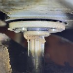
On closer inspection, I found what appears to be a circlip/stopper ring immediately above the splined end of Shift Rod A, as shown in the attached photo. Could this be item #13, the “Ring, Stopper,” shown in the parts diagram?


Is this ring supposed to be removed to allow Shift Rod A to drop downward, or is the rod intended to pull through with the ring still installed? My concern is removing the ring and then being unable to reinstall it from this limited-access area.
 

Attachments

  • Shift A circ clip_resize.jpg
    Shift A circ clip_resize.jpg
    528.3 KB · Views: 3
I initially pointed out that "stopper" (item 13) in my first reply. You must have not seen that I think that ring is to limit how far the shift rod inserts into the shift shaft and has no function to hold the two together.
 
I see your comment in the first reply:
I believe #13 "stopper" just limits the spline engagement depth and doesn't hold the shafts together.

I didn't miss it but it didn't register as I looked at the circlip.

It's the old saying: "I see says the blind man":mad:
 
Back
Top