Are you suggesting that each harmonic balancer decal is installed in the same direction from the TDC mark???? IOW, when you strobe your timing marks, are you seeing the same advance direction at either engine????
Do you have a Std LH Rotation engine and a REV RH Rotation engine..... or do you have a reversing transmission on the Stbd side????
IOW, do you have two Standard LH Rotation engines?????
As I mentioned earlier, you really need to see your OEM ignition curve information, and if that means contacting Crusader, that's what I'd do.
28* @ 3k rpm may be OK for a quench built SBC, but may be perhaps a bit much for a non-quench build.
However, if you did detonate this under load, and for any length of time, you would have certainly sustained damage.
Detonation that has not yet caused damage, will indeed hurt performance, but we rarely escape damage if allowed to continue for any length of time. It is also rather silent compared to pre-ignition, and when in an enclosed engine bay, it can be difficult to hear audibly.
In post #12, you mention "None of the issues that have been presented here were occurring PRIOR to the conversion to the electronic ignition kit". My guess would be Pertronix kits???
The Pertronix kit, IMO, is a rather cheesy way to obtain electronic triggering. You'd need to read quite a bit on this to fully understand why I suggest this.
Good news is, your mechanical advance units appear to be working in that a BASE of 10* offered the advance of 28* that you were seeing.
Good news #2, is that both ignition distributors did the same (although that 28* needs to be further discussed, IMO).
Your friend who did not re-time his ignition after the Pertronix install, either doesn't care much, or he was very lucky.
You, on the other hand, are smart for having done so.
")
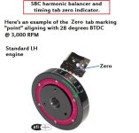
1.... If I applied the stickers correctly I got them both at 10*. When they advance they max out at 28* around 3k RPM. Here is where I may be missing the curve.
2.... If I can lay out my logic here – I set the base at 10* on idle running around 700 RPM. I accelerate the engine to 3k RPM and I see the advance max out around 28*. These are the 2 numbers I have heard over and over. Since I start at 10 and it maxes at 28 am I done?? No further adjustments? Say it maxed out at 22* (and I know it needs to be at 28*) would I advance it to get to 28*? Or when I’m at 28* on 3k RPM do I then have to retard it back 10* to get to 18* at 3k RPM (subtracting the original 10* from base). I think this is where I’m off, I don’t really understand the “curve”. I guess my main question is do I need to adjust the distrib once its 28* on 3k RPM? Or do I leave it there? If I leave it there then I really didn’t make any adjustments short of the original base at 10* - which im hearing is not the most important number. Does that make sense? I wish there was a “timing hotline”! lol.
We'll be your "timing hot line"! LOL
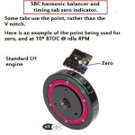
1... are you absolutely certain that the decals that you purchased are the correct decals for your balancer diameter????
If not, the degree scale will be inaccurate.
2... Your logic sounds good.
Short of actually plotting out your curve, setting your BASE of 10* that rendered a TA of 28* @ 3k rpm, sounds like you understand this.
To understand the curve, look at the advance curve that I posted earlier.
Note where the advance is at the various RPM.
Remember..... this graph is minus BASE, so when you read the scale, BASE must be added.
Let's use the dark line and assume that a BASE of 10* is correct!
NOTE: do not use this dark line curve for your engine without knowning about the build.
At idle, you'll see zero advance, however, the engine is actually seeing BASE of 10* at this point.
Now look at 1k rpm. You'll see 2* of advance. Add your BASE of 10*, and the engine is actually seeing 12*.
Now look at 2k rpm. You'll see just over 10*. Add your BASE of 10*, and the engine is actually seeing 22+*.
Now let's go to 4K rpm. You'll see that the curve has already flattened out by 3.4k rpm.
At 4k rpm, the advance is now near 22+*. Add your BASE of 10*, and the engine is actually seeing 32+*.
I've skipped some.... but you get the idea.
So, we have BASE advance (no mechanical advance yet), a progressive advance (of which in your case is mechanical), and a Full In advance (or aka TA or total advance) of which is a combined advance of both BASE and Mechanical.
(EST systems are another topic, and function somewhat differently)
Bottom line..... if the BASE advance is suitable for firing on, and idling on, and if the progressive is rather linear, and if the TA comes on no sooner than at the correct Full In RPM, you should not need to make further adjustments.
But again..... your numbers need to be verified via Crusader, IMO.
As Mark said, make sure that you do not have a lean high speed F/A mixture. That alone can cause issues.
.