Logo

Boat supposed to have an ignition module??

birdy916

Member
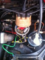
Quick question guys. I have a 1979 mercruiser 898 with a thunderbolt iv ignition module. My friend jus recently bought a boat too and its hard to start. He has a 1979 mercruiser 260 which should pretty much be the same setup as mines correct? But he doesnt have an ignition module. Is he supposed to have one?? Thanks!
 
Ayuh,.... 1979 was Along time ago,...

Time enough for somebody to have removed the T-Bolt IV that oughta be there...
 
Well i just went and looked at his distributor and mines. they are different. mine has the 2 nuts where the 2 wire leads connect from the thunderbolt. his distributor doesnt have that. so i'm assuming his distributor is incorrect then? or if we get a thunderbolt module, we'd have to get the correct distributor as well?
 
Incorrect...maybe not, but definitely not a TB-IV. You will find them to be very hard to get as new items and used or rebuilt ones usually get a premium. What's important is that the distributor be rated for marine service and has the correct advance curve in it. If you bud's dizzy is in need of replacement you may wanna consider the mallory marine or the GM EST units. Both are marine rated and usually available as turn-key kits.
 
The TB IV is an early version of EST (electronic spark timing).
I too don't believe that this was an option in 1979.... I could be wrong.

If there is no mechanical advance mechanism in the distribor housing, then it may be a Thunderbolt.
If it has a mechanical advance mechanism, then it would not be a Thunderbolt.

Ditto Mark and Chris on the Mallory Marine.
My preference is the VR triggering over that of photo-eye.... (YLM vs YLU).

The GM that Mark mentioned would be EST.
 
Last edited:
Ok thanks guys. i'm still tryna find out why the boat wont start. cranks and all. gets plenty of fuel.

We need to find out what ignition system you have before we can advise you on what to check. Remove the distributor cap, take a picture, and post it. This will take the guess work out.
 
hey guys, here are the pics to mmy buddies boat. i changed the spark plugs and after a few tries i finally got it working. i guess the spark plugs werent in the correct order so i turned the crank pulley and got it to tdc and redid it so that it fired up in 1-8-4-3-6-5-7-2 order. when i put it on tdc, the rotor was at the 630 position and i also stuck a piece of napkin into the #1 spark plug hole and it blew it right out before i got to the tdc. that should all be correct right?

photo 2.jpg
photo 01.jpg
 
Last edited:
Yup, Looks to be a point system, w/ 1 wire going to distributor.

TDC is absolutely # 1 cyl on top of compression stroke, point rotor to # 1 Cyl, then follow correct firing order in "the correct" rotation.
 
Birdy, from what I can see, that is definitely an old points style, mechanical advance Mallory distributor.
The single wire, brown cap and hold-down clamps say so.

The additional wire connected to the - side of the coil would normally be white. This would be the tachometer lead.


I would do as 04fxdwgi suggests.
Begin at #1 cylinder TDC C/S, and re-set the distributor so that the rotor is aiming towards #1 cylinder (although it does not need to be indexed this way... but most do!)

Then wire the cap in the CW direction from #1.
Set BASE advance, then check the progressive advance and see what it's doing at the TA rpm.

IOW, DO NOT assume that this old distributor is offering the correct progressive advance ..... varify this for yourself!

If this Mallory is OK, he won't have any issues with it, other than occasionally replacing contact points and setting dwell.

Personally, I'd rather have this Mallory than the older Thunderbolt system. Much easier to trouble-shoot should he have a problem.
 
Last edited:
Birdy, from what I can see, that is definitely an old points style, mechanical advance Mallory distributor.
The single wire, brown cap and hold-down clamps say so.

The additional wire connected to the - side of the coil would normally be white. This would be the tachometer lead.


I would do as 04fxdwgi suggests.
Begin at #1 cylinder TDC C/S, and re-set the distributor so that the rotor is aiming towards #1 cylinder (although it does not need to be indexed this way... but most do!)

Then wire the cap in the CW direction from #1.
Set BASE advance, then check the progressive advance and see what it's doing at the TA rpm.

IOW, DO NOT assume that this old distributor is offering the correct progressive advance ..... varify this for yourself!

If this Mallory is OK, he won't have any issues with it, other than occasionally replacing contact points and setting dwell.

Personally, I'd rather have this Mallory than the older Thunderbolt system. Much easier to trouble-shoot should he have a problem.


I see he has 3 waires attached to the negetive side of coil. 1 to the points, one to the tach and I am assuming the 3rd wire is the ignition interupt for the shifter. If it's not the interupter, then I would suspect that 3rd wire. For a test, I would disconnect the 2 that don't go to the distributor and see if it runs. If it does, then some troubleshooting of the other 2 is in order.
 
Well so far i did wat u guys said.
set to tdc
photo 1 (1).JPG
then did the firing order 1-8-4-3-6-5-7-2,
photo 2 (1).JPG
starting at where the rotor is pointing. still no luck, cranks but still wont start. getting fuel and spark. got new spark plugs, still nada. gonna order a new cap and rotor since i dont know how old the current ones are. and other suggestions?? thanks!
 
Well so far i did wat u guys said.
set to tdc
View attachment 4339
then did the firing order 1-8-4-3-6-5-7-2,
View attachment 4340
starting at where the rotor is pointing. still no luck, cranks but still wont start. getting fuel and spark. got new spark plugs, still nada. gonna order a new cap and rotor since i dont know how old the current ones are. and other suggestions?? thanks!

Questions...
1. How old is the gas?
2. Did you change the condenser in the distributor?
3. Are you sure you are getting gas THROUGH the carb into the intake? (there may be a little filter in the carb inlet that could be dirty).

Observation:
How can you possibly have spark. The green wire to the distributor is disconnected.

Suggestions:
1. Disconnect the all wires from the distributor.
2. With a meter or test light, find out which one has power on it when key is turned to ignition.
3. Connect that hot wire (and only that one) to the coil B+
4. Connect the green wire from distributor (and only that one) to the coil B-
5. Put a new condenser in it.
6. If you have a Tach / Dwell meter, connect the red connector to the B- of the coil and the black connector to ground, turn the meter to Dwell 8 cyl and crank the engine. If you have good points / condenser / coil and power, the dwel should bounce around when you crank the engine.

Try to start it then.
 
1. The gas i am not sure but the tank was empty n filled with new gas with 7 gallons.
2. Havent changed condenser but hoping to this week including cap n rotor.
3. yes its getting fuel. can hear/see fuel shoot out wen throttled.

i disconnected the green wire because there was already another black wire frm neg coil to distributor ground. but if its supposed to b connected i will reconnect. also before all this i changed the impeller in the outdrive.
 
Yea i dont know y but theres 2 wires connected to the negatve of coil and to the points. Should i take 1 off?? The green one??

Birdy, remember that #1 TDC comes around twice for any 4 stroke engine. This is why you'll see #1 TDC C/S. ........... C/S = Compression Stroke.
This must be #1 TDC C/S , or your firing order will be out by 360 degrees crankshaft angle, or 180 degrees distributor angle.

Where does this green wire connect????? An external condenser by chance????
Can't see it in the photo.
If the green wire connects to an externally mounted condenser, remove the green wire, and install a brand new correct condenser in the distributor.


I'll ditto the comment re; setting the points via a dwell meter.
Setting contact points via gap is an estimate ONLY of correct dwell..... and dwell is what you want... not gap.


Also, and since this is Mercruiser using the SA system......., temporarily disconnect the SA lead.
You don't need the SA when test running the engine.
The SA is for assisting in a Dog Clutch shift from gear back into Neutral.... nothing else.
If the cam lever and/or micro switch are not adjusted correctly, it will affect your ignition.
By temporarly disconnecting this, you can eliminate the SA as being part or all of the igntion problem.


Edit:
BTW, Birdy, the comments regarding the rotor physically aiming towards #1 cylinder is an option.
Most of us will phase or index our distributors this way, but it's not a deal breaker as long as your spark plug wires are indexed correctly as per the firing order.
IOW, the rotor could be aiming in any orientation..... just wire the cap correctly, and the engine won't know the difference.

Just a heads up on that! :D

Again, after setting BASE advance, be sure that you look at the progressive advance.

.
 
Last edited:
yea i've gotten it to the #1 tdc c/s. i stuck a piece of tissue in the hole and it spit right out after i spun the crank.


as for the green wire, like i said, it looks like jus an extra wire that connects from the -coil to the distributor, jus like the black wire. thus i disconnected it since there was already a black wire. so there is no external condenser.


i will c if i can get ahold of a dwell meter.


wat is an SA system and where is the SA lead??


as to the phase or index of the distributor. thats wat i thought so as well since there is no marking on the cap as to which is #1, so as long as its on tdc and i have the firing order on the cap correct to where the rotor is pointing then like u said, the engine wouldnt make any difference so i should b fine there.
 
The compression stroke is when the piston is coming up and BOTH valves are closed. Just because a piece of paper blew away from the spark plug hole do not assume it is on the compression stroke. REMOVE the valve cover, watch # 1 intake valve open then close, when closed that is the compression stroke.

This is when you line up the timing mark as you did to ZERO. Now pull ther cap and the rotor MUST be pointing to number one spark plug wire period.

if this is true and you have fuel and spark the it MUST fire. do you have any idea what the compression is? if it is too low it may not fire!!

The "SA" bieng refered to is what is commonly called the "SHIFT INTERUPTOR SWITCH" it is the micro switch with the white litlle roller end in the middle of the V notch. (behind your distributor) This switch has two wires, one to ground connected at a terminal block and the other to the - (negative) of the coil.

This is a normally open switch, when the V notch moves (when shifting out of gear only) it will make/close the switch. when this occurs it grounds out the ignition for a split second so the lower unit gears/shift dog seperate.

If this is not working then shifting out of gear is almost impossible, if it is shorted or activated closing the switch then NO SPARK!!!!

The green wire is a replacement wire and NOT factory. It may have been replaced somewhere along the way.

How do you know you have spark? Please explain.

Remember we are not there and it is best to assume you do not know what you are doing until you can prove/explain how and why you have done or concluded your results but still no fire..........
 
Last edited:
1.... The compression stroke is when the piston is coming up and BOTH valves are closed. Just because a piece of paper blew away from the spark plug hole do not assume it is on the compression stroke. REMOVE the valve cover, watch # 1 intake valve open then close, when closed that is the compression stroke.

2... This is when you line up the timing mark as you did to ZERO. Now pull there cap and the rotor MUST be pointing to number one spark plug wire period.

3.... Remember we are not there and it is best to assume you do not know what you are doing until you can prove/explain how and why you have done or concluded your results but still no fire..........
Kghost is right on regarding the SA.
If this is not working correctly and is interrupting when it should NOT be interrupting........ NO SPARK... period.


1... Good point. Tissue paper would not be the best method for this.


2... Kghost, I fully agree that this is the correct way to set one up. You are I would certainly take the time to re-index the distributor.
Unless the distributor cap is marked 1 thru 8, and unless the owner intends to maintain those markings, this is not necessary.
The rotor could be aiming any one of any directions.... and for as many teeth as there are on the distributor driven gear.
The key would be in the orientation of the spark plug wire indexing.


3... Fully agree. Trouble shooting via mouse and keyboard is rather difficult.


yea i've gotten it to the #1 tdc c/s. i stuck a piece of tissue in the hole and it spit right out after i spun the crank.


as for the green wire, like i said, it looks like jus an extra wire that connects from the -coil to the distributor, jus like the black wire. thus i disconnected it since there was already a black wire. so there is no external condenser.


i will c if i can get ahold of a dwell meter.


wat is an SA system and where is the SA lead??


as to the phase or index of the distributor. thats wat i thought so as well since there is no marking on the cap as to which is #1, so as long as its on tdc and i have the firing order on the cap correct to where the rotor is pointing then like u said, the engine wouldnt make any difference so i should b fine there.

By connecting everything as I suggested, you will only be connecting only the ignition circuit and cutting everything else out that could possibly be causing a problem. Once you get her running, then you can move to finding what is causing the problem, such as the tach (could be bad and failing the ignition) or the interupt switch (which can also be shorting out the ignition).. There should be only 1 wire going from the distributor to the coil neg side, green one or black one, doesn't matter, but just 1 (get rid of the other one, because if that green wire is left connected to the dist and is touching any ground point, it is shorting out the ignition). Check the connection point on the distributor, as I have seen them ground out, also. The neg side of the coil goes to the points, not a ground. Ground that wire and it will burn up the coil in short order, if left grounded with 12 VDC applied for any length of time.

If you have fuel and if the distributor is set at TDC (#1 cyl at top of compression stroke with both valves closed) and rotor pointing to cyl 1 and the points and condenser are good with 12 VDC applied properly, she should fire, or at least make some sort of attempt to. The points systems are pretty straight forward with very few things to go wrong, unless there are other mechanical problems, like a jumped timing chain or something of that nature.
 
Last edited:
Birdy, can we ask you for some clarity on a few things here?
Where is the green wire now?
Where is this black wire actually connected?
Do my broken yellow lines show the black wire?

Which sides of the coil are marked + and - ? (I can't quite make it out in the photo)


As 04fxdwgi said, the - side of the coil goes to the contact points and condenser.
This is also where you'll see the SA and Tach connected.
Do as he suggests, and temporarily disconnect the SA and Tach.

The + side is the power side, and will connect to your ballast resister if so equipped.

The contact points (along with the condenser) take the - side of the coil to Negative (ground) when closed.
When the points break (open) is when you'll get your secondary high voltage spark at the high tension lead.

If you were to use a non-conductive tool, you could actually open/close the contact points manually to check for secondary high voltage spark.
You'll also be able hear the spark in the event that you can't see.
Ultimately you want to see as to determine the quality by color.
White/blue-ish is what you want to see....... yellow-ish is a weak spark.


04fxdwgi brought up a good point about the Mallory connecting terminal isolator... (see red arrow above)
This is nothing more than a small machine screw isolated in a 2 pc plastic unit to prevent contact with the aluminum housing.
You may want to pull this apart and clean it up.

Here is a basic automotive points style ignition system. Schematically it will be similar to your points system.

,


Attachments

  • Birdy green and black wire Ignition issue 2.jpg
    Birdy green and black wire Ignition issue 2.jpg
    73 KB · Views: 4,007
  • Ignition Diagram with initial timing test.gif
    Ignition Diagram with initial timing test.gif
    34.1 KB · Views: 43,441
Last edited:
the green wire is not connected to or touching any ground at all. the black wire is from the - coil to the distributor jus how your drawing yellow dotted line is. the + coil is connected from the ignition/battery and has power wen the key is turned on. last nite i uplugged the SA and Tach from the - coil and left the black wire from the - coil connected to the distributor. wen the engine is cranked and cap and rotor is on, there is no spark at the main coil (i used a platic holder kind of like pliers but all plastic, holding it about 1/4" or further away from a ground bolt(confirmed it has ground by using a trouble light to connect that bolt to the + battery and the bulb comes on), cranking the engine, there is no spark from the main coil plug to the grounded bolt. but if i take off the cap and rotor and leave the key on, manually open/close the breaker points and still using the plastic holder with the main coil close to the grounded bolt, i see spark from the main coil from the igniter and grounded bolt. wat do u guys suggest is wrong?
 
In this 6 cylinder distributor image, you'll see where I show an alternate coil testing method.

Grab an old but good spark plug wire, and place it directly into the high tension port of the coil.... not the distributor cap!
Forget the normal coil-to-cap wire for the time being.... it will go back in later.

Now place a good spark plug into the wire, and give it good negative contact to the engine block.
Be sure that the spark plug is gapped correctly.

This way you should see 8 spark events .... not just one spark event for every two crankshaft revolutions.


Like said earlier, you can also manipulate the contacts points with a non-conductive tool without turning the engine over.

Each time that the points "break", you should see a spark event.... and a good white/blue-ish one.


NOTE: the contact points much be clean and make good contact.
If they are NOT making good contact, the coil will not undergo saturation... of which is actually the dwell time or dwell angle.

The whole idea is to saturate the primary winding of the coil (points closed) and allow the condenser to store the energy.
When this primary field collapes (points open), the secondary high voltage is released to the spark plugs.


.
 
Back
Top