Logo

72 Johnson 65hp hydro shift CDI voltage regulator rectifier wiring HELP

tawas23

Member
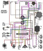
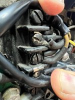
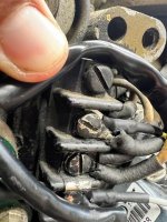
I have a question on installing a CDI regulated rectifier part number 193-3408 and a 1972 Johnson 65hp I do have a wiring diagram and have most of it figured out except one yellow wire and one gray from regulated rectifier tach wire should I hook them both gray and yellow up to my tach output number 3 on terminal block or just one yellow and no gray or just gray with no yellow plz see picture any help would be great thanks
 

Attachments

  • CDI 2.jpg
    CDI 2.jpg
    122.9 KB · Views: 184
  • 1972_65_Eshift.jpg
    1972_65_Eshift.jpg
    236 KB · Views: 417
  • CDI.jpg
    CDI.jpg
    122.9 KB · Views: 448
Thank you Fazbullet so the yellow wire in question will go to terminal 3 that runs to tach sending terminal at gauge and the gray wire that CDI says is for the tach wire cap that off and I should be good just to reiterate. Thanks again for the help
 
Also I wanted to ask would it be wrong to attach both yellow and gray tach wire off the CDI regular rectifier to same #3 terminal to tach gauge or just use the yellow wire as you stated and be done with it?? Not sure why CDI would have 2 wires that could run the tach installation says run gray to tach and if tach doesn't work run the tach wire to yellow wire not very good instructions that's why I am here for much needed help thanks
 
OK I have this diagram that hopefully will make my question easier to see my issue.my terminal block is wired exactly like this diagram the only issue I have is my new CDI rectifier regulator has one more wire that I am not sure where to connect to the tach?? The old rectifier has 2 yellow wires one yellow goes to #1 terminal with one yellow stator wire and one yellow diode shift wire as shown on diagram total 3 wires on terminal #1.Now terminal #2 has 2 wires.. one yellow with gray stripe from stator and one diode wire that's also yellow with gray stripe. Now my issue is terminal #3 one gray wire to tach gauge.. My new CDI has one yellow wire and one gray wire in question.. CDI says gray is Tach wire so my issue is connect both yellow and gray together to terminal #3 total 3 wires???? or just one the yellow or just the one gray?? either way I will have one wire on New regulated rectifier that's not used if I hook one or other. Hope this helps
 

Attachments

  • 65hp.jpg
    65hp.jpg
    398.9 KB · Views: 151
Terminal #1 has one stator wire with one rectifier wire and one shift diode wire only 3 wires total.. #2 has the other stator wire with one shift diode wire not at all connected together.2 separate terminals not connected together at all not sure how you see that???disregard pic as cannot see them at all in pic the wire diagram shows exactly how the wires are connected that why I have the diagram only on last pic.
 
Wow!!!! I just looked at that again and your right I see it now but what do I do with this new info it still doesn't tell me what to do with my one yellow and one gray coming from new CDI why is that not on the wire diagram?? Thank you for showing me this can you tell me where to connect the 2 wires in question now one Yellow to what terminal and gray to what terminal. Your awesome I like learning new things you got my attention for sure 2 and 3 are connected..
 
OK I was hoping to avoid that as I did call last week and he said remove diode wires but he didn't have wiring diagram to see what I was talking about hopefully I can convince him that's not a good idea on a hydro shift outboard but I will try again to call him and hopefully get a better answer thanks again for pointing that out helps alot. I thought adding this was as simple as it was on my Mercury I did years ago but guess not.
 
Your pictures in post #1 are correct. Gray tach signal could be taken from either yellow stator wire (both are AC), However, the new regulated rectifier senses the output (red) voltage and if too high it momentarily disables one side of the AC (yellow) input This means that if the tach was reading the pulses from the wrong AC input you would be getting erratic tach readings as the regulator disables/enables that input. CDI wisely made the connections inside the rectifier unit so you wouldn't make that mistake. Easy to understand but hard to explain in writing. At least for me.
 
OK answering this so I hope it helps anyone else that would have this issue .I called CDI and sent him my wiring diagram and this thread and he said terminal #1 gets a yellow wire ..terminal #2 gets yellow wire ..terminal #3 gets gray wire from the regulated rectifier. Thanks for the help I got from here.
 
Back
Top