Logo

1976 351w running very rough after top end reassemble - aaargh!!

Dont care what you or anyone else thinks of my attitude.
Most who reply on this forum reply to OEM specifications.
We do not speculate on a million possibilities that some may have done something to a 40 year old boat....we follow the factory manuals.

That is what trained marine technicians do.

If it is not OEM....in most cases.....your on your own...

Just like going to a auto dealer...they do factory only repairs.
Not vehickes that have been altered...

Most of us answer based on the same assumtions. The boat engine is still OEM.

So speculating on cam changes and NOT setting the wiring and location of number 1 is wrong.
It should at all times be made to or put back to original OEM specs.
That includes the wire locations on the distributor cap.
What i would suggest is get a OEM factory manual so you have the correct information.

So far you have shown you have niether.......


100 Xs on this.


FYI, If the distributor is clocked incorrectly. the ignition wires will not fit correctly.
 
Last edited:
If it was me I would check for slop in the timing chain. With a socket wrench put the timing mark on TDC and watch the rotor on the distributor and turn the crank backwards and watch the rotor until it just starts to move. Anything over a few degrees and the chain and sprockets need replaced. If the timing chain is good find true TDC with a piston stop tool you must confirm true TDC to continue with the tuneup. Base timing is not as critical as all in or total spark advance especially on a older distributor. Set the points at the proper dwell angle point gap will get you home but dwell is used for best performance. Allways adjust base timing after you set the dwell angle. One thing has not been mentioned is it may be possible the engine is counter rotation confirm you have the correct firing order for the engine your working on.
 
I found a manual at boatinfo library here are a few specs
left hand rotation firing order 1-3-7-2-6-5-4-8
right hand 1-8-4-5-6-2-7-3
dwell angle 26-31 degrees and 10 degrees base timing
The advance curve is real aggressive at first and then levels out dual spring tension fly weights
Mechanical advance is 20 degrees at 1600 rpms then max advance is 27 degrees at 4000 rpms
That is without base timing so you can adjust all in (base timing plus mechanical advance) at 37 degrees at 4000 rpms to be safe sou your not gonna cook valves and pistons with detonation. Do not earball it you can cook the engine real fast. That gets back to true TDC without it your playing with dynamite.
 
Pretty sure Ford cams are interchangeable between 302, 351w, 351c and all ho versions. I would assume nothing at this time is original because of all the problems encountered. Jack is correct in stating set dizzy at factory setting. Leave all wire off but number one, rotate motor by hand and verify firing order by following rockers, firing order is determined by camshaft only. Depending on what cam is in there could have multiple possible firing orders, been there done that. Verify rotor rotation and set wires accordingly. Good luck, and remember people are here to help, we need all the info and all things done so that the correct resolution can be found
 
Another option, get it running best you can, at idle start pulling plug wires, find a pair that don't fire, switch those plug wires at dizzy and see what happens. Would recommend insulated plug wire pliers and rubber gloves! Can't hurt anything as long as you have water flow through the cooling system. If you have an even number of cylinders misfiring then its crossed wired, odd number other problems.
 
The distributor does not know what cylinder is #1 one trick is to put the timing light on each wire until you see the timing marks. use that wire on the tower for #1 cylinder and set the firing order from there. If the engine does not run just rotate all the wires 180 degrees and it should run. Ideally you would put your finger in the #1 plug hole and rotate the crank until you feel compression and then line up the timing marks to TDC. Look at your rotor it should be pointing in the 11 oclock position looking at the front of the engine. If not lift the distributor and turn it so it points at the 11 oclock when it is all the way down. It can take a few times because you need to rotate the crank to get the oil pump to line up so the distributor drops all the way down so just take your time. Once you get it right then you have the 11 oclock reference point for future tuneups to put the plug wires on correct if you get them mixed up.
 
..."Pretty sure Ford cams are interchangeable between 302, 351w, 351c and all ho versions.""

NO! Ford used two different firing orders for 302s (at least) and the cams do NOT interchange.

Jeff
 
Let's see if we can't help simplify things for Mr. FstaRockr Burns and do it in a kind and adult like manor. (Jack..... please drop the attitude)


Mr. FstaRockr Burns, the P of E (process of elimination), when used methodically and systematically, will not let you down!
I suggest that you use it so that you can get things sorted out quickly!


This is what I see here:


You may be unclear as to the firing order for this 5.8L Ford engine.

You suspect that the outer harmonic balancer ring may have slipped on it's inner hub.

FYI...... w
ith cylinder heads in place, you need to perform the PPS procedure (PPS = positive piston stop).
Using a screwdriver throught the spark plug port is not the correct nor accurate means to determine TDC!


With the now Verified and Re-Marked balancer..... mark if off again in 90* increments from the NEW verified TDC marking (use a white paint pen).


You know where #1 cylinder is (furthest forward Stbd side).
You know how to bring #1 cylinder to TDC on the C/S..... do it at this time!

Make certain that the distributor's rotor is indexed to the #1 cylinder's cap tower!
Place this cylinder's spark plug cable into this cap tower!


Now with the valve covers removed, rotate the crankshaft in the standard LH Engine rotation direction.
(this will be CW when viewing from the front of the engine)


Watch for the "next-in-sequence" Intake valve to complete it's cycle and to close.

As you bring this "next-in-sequence" cylinder to or near TDC, the 90* marking will align (it can be close ONLY).


This will be your next cylinder in the firing order!
Place this cylinder's spark plug cable into the corresponding cap tower CCW from the #1 cap tower.


Repeat this process until you have gone through all of the remaining 6 cylinders.


****************************************************


For initial start-up, bring the #1 cylinder around to 6 or 8 degrees BTDC on it's C/S. (this will simulate BASE or Intial advance)


Place a known-to-be-good spark plug in the boot of #1 cylinder spark plug cable.
(make sure that the spark plug body contacts a metal component and that you have NO gasoline vapors present!)


With your ignition distributor hold-down clamp somewhat loose, rotate the distributor in a CCW direction (past the #1 firing point).

Excite the ignition system (turn the key ON).

Now rotate the distributor in the CW direction until you see 1 spark event.

Repeat this until you are able to stop rotating it immediately upon seeing the spark event.

Now lightly tighten the hold-down clamp bolt.


This will get your spark events close enough for initial start-up.


FYI, If the distributor is clocked incorrectly. the ignition wires will not fit correctly.

Yes..... if using a pre-cut-to-length spark plug cable set!

Personally....... when @ #1 TDC C/S, I prefer to see the rotor aiming towards the physical location of #1 cylinder!

Otherwise, like Kim said........ the distributor doesn't care how the cables are set up as long as they fit, and as long as the indexing and firing order are correct.


Did you remember that # 1 plug is on the left side of the motor? Drivers side!!
For a Ford 351W I/O, that would be the Starboard Side of the Engine!

When talking boats....... Fore/Aft/Port/Stbd leaves little room for misinterpretation.

.
 
Chris, re-read post #39!
I am agreeing with you in that these would (or may be) PRE cut to length.

If these are the style that would be custom cut to length, then it does not matter where we index the #1 ....... as long as they are all indexed correctly.


.
 
Sheesh! This is getting a bit long toothed.

If all else fails, one can always remove the valve covers and crank the motor over with a breaker bar to determine the firing order. Just watch for the intake valves to open and jog down their location.

I've had to do this a few times with some Mercury triple OBs (that had two different firing orders). In this case I used the "Phillips Indicator" (screw driver in the plug hole) to see which piston came up next.

Jeff
 
..............................
Sheesh! This is getting a bit long toothed.
Yes..... I agree.
I see several problems here:
1..... the OP is inexperienced (no offense) .... and 2..... the OP is not using any organized P of E.


If all else fails, one can always remove the valve covers and crank the motor over with a breaker bar to determine the firing order. Just watch for the intake valves to open and jog down their location.
Yes..... I gave him a detailed "How-To" in post #39.

I've had to do this a few times with some Mercury triple OBs (that had two different firing orders). In this case I used the "Phillips Indicator" (screw driver in the plug hole) to see which piston came up next.
"Phillips Indicator"...... now Jeff......., I like that one!

Seriously though.......... for the 5.8L Ford W engine with a potentially slipped balancer outer ring, the PPS and degree wheel will be much more accurate!

 
Considering the collective time the paid experienced professionals have put in on this guys, (1976 obsolete Ford which is beyond its service life and should be junked because it will never run correctly), We could have repowered his boat with the lost wages.
 
Considering the collective time the paid experienced professionals have put in on this guys, (1976 obsolete Ford which is beyond its service life and should be junked because it will never run correctly), We could have repowered his boat with the lost wages.
Twice. Nothing you get for free (or cheap) ever is.
 
Considering the collective time the paid experienced professionals have put in on this guys, (1976 obsolete Ford which is beyond its service life and should be junked because it will never run correctly), We could have repowered his boat with the lost wages.

What I concluded was he has experience but moves way to fast and isn't careful enough to watch his steps.
He takes one step forward and two steps back for every task he takes on.

He is researching the internet for answers he does not need.

It is not rocket science to tear down a engine to the level he did and put it back together with no running issues.

He did 20 things all at once with no traceability backwards to understand what he may have done wrong.

IE; is it ignition, carb, bad intake gaskets (not lined up) constantly second guessing his work and not really following advice.

How many times did I say, no difference in firing order for any of the ford engines used for that year????

But the questions and "diagnosis" he kept spewing about some how this engine had a transformation into a completely different animal from OEM.........
Maybe it did but from the looks of the parts he removed told me that engine has been together for a long time.

Looking for problems that may not have existed............never going to fix it that way.......
 
Well got everything up and running - have no clue, only thing i changed was plugs and confirmed the firing order was indeed stock. Anyways glad to be back up and running - motor is super smooth and power is back. Will set dwell etc now ..

Also i noticed there are 2 stats in my intake manifold - was this stock? Im thinking of wiring up a higher temp stat and using that as an alarm if its not stock..


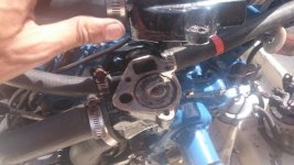
Just a quick check - is this the correct position for the stat? Had some heating issues so killed it before it got hot - anyway, changing the rear impeller now too. I presume the lower water pump pumps water up into the motor? only have muffs too - maybe ill fill a tank and try that rather..

DSC_0531 (Copy).jpg

thanks
 
Thanks for the advice - was considering sierra, but the impeller was so melted the water pump housing roof was coated in very hard to remove impeller material that had been melted. West marine didnt have a full sierra kit so got the quicksilver for peace of mind (since its the heart of the motor) - installed and shes running beautifully. Dwell at 29 - temps perfect.. good sweet smell from exhaust - super responsive. Finally home -

fyi the issues i had were old gas in the tank. So hard to start - drop in a bot of denatured alcohol and she fires up instant.


tx for all the input - glad t be back up and running.


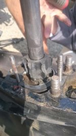
the old adage - "she was running beautifully". yeah whatever - the dead heart valve:

DSC_0537 (Copy).jpg
 
I repair HVAC and I have to bite my tongue every time a customer say it was working great last year, why is it not working now? My first question is how often do you change the oil in your car? Not all furnaces break from lack of maintenance but 98% of those that break were not maintained properly.
 
Is it me or does that engine and thermostat design look like an OMC motor.

I questioned the looks of the exhaust manifolds in an earlier post.

The Motor was repainted Blue which was OMC's color.

It would appear to me that someone retrofitted a OMC motor into this boat.

Only things needed to be changed would be bell housing and coupler and motor mounts..............

Virtually all the rest would be a direct bolt in..............

Anyone else agree?
 
Well got everything up and running - have no clue, only thing i changed was plugs and confirmed the firing order was indeed stock. Anyways glad to be back up and running - motor is super smooth and power is back. Will set dwell etc now ..

Also i noticed there are 2 stats in my intake manifold - was this stock? Im thinking of wiring up a higher temp stat and using that as an alarm if its not stock..


Just a quick check - is this the correct position for the stat? Had some heating issues so killed it before it got hot - anyway, changing the rear impeller now too. I presume the lower water pump pumps water up into the motor? only have muffs too - maybe ill fill a tank and try that rather..

View attachment 15037

thanks

NO only one thermostat. and it is in the thermostat housing NOT the intake manifold.

What you need is a temp switch which looks like a temp sender but is a switch. This is how late 90's into the 2000's mercruisers are set up. The temp switch is wired to the alarm circuit as is Low gear oil (reservoir) and oil pressure switch.
 
Is it me or does that engine and thermostat design look like an OMC motor.

I questioned the looks of the exhaust manifolds in an earlier post.

The Motor was repainted Blue which was OMC's color.

It would appear to me that someone retrofitted a OMC motor into this boat.

Only things needed to be changed would be bell housing and coupler and motor mounts..............

Virtually all the rest would be a direct bolt in..............

Anyone else agree?

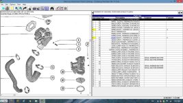
Looks like Mercruiser.

Untitled.jpg
 
Mr. Burns...... I must agree with the guys here....... that dual T-stat housing is old school. It stinks of becoming problematic!
 
Last edited:
yeah well i have to check everything.. or install sth to alert me - no sign of an alarm anywhere yet.. I inspected the lower unit and seal - it was in great shape.. I replaced the impeller housing, plate and all the parts / gaskets incl the oil oring.

Pumps water like crazy - the muffs dont even leak a drop. Had her running for 30 mins - temp gauge stayed put around 45% in the green.

Will be doing some elec testing today - the starter solenoid is also a bit crummy (secondary?) - doesnt always activate the starter so will clean connections and put on some die electric there..

oil is perfectly clean - not a sign of a drop of water either.

As mentioned before just no money or patience to repower - im not dumping $ at all (not in boating standards anyway) -


So my temp switch is wired on the starboard side gauge - what is the 2nd one for then? backup / alarm? Sorry i meant tmp switch - not stat in prev post.

Id like to have an alarm if the needle hits the red.. maybe wire in a tmp switch on the intake manifold (which i presume is what the 2nd switch is for) - what would an alarm temp be, like 180 perhaps?
 
A temp SENSOR/SENDER is a variable resister. ~ 120 ohms to ~ 320 ohms. Could be more or less based on sender design.

A temperature switch is a switch. When it reaches a designed set point it will close and short to ground and cause the alarm if such an alarm is present and is typically under dash but also typically on 1990 ish and newer boats.

Your boat and most in the 70's had no such alarms.

so I have no idea what the second is. One will read ohms and change with heat/cold. the other will show an open and when a certain temperature is reached will read closed.

Your engine should have two senders. Oil and temperature only

It is very very common that the SLAVE solenoid to fail This is a second stand alone solenoid (if your starter has on mounted to it). The typical symptom is it only clicks when key is turned.
 
Back
Top