Logo

2010 BF50D Fuel Pump issue

SaltTime

Member
Ive recently purchased a bf50d outboard and have been troubleshooting and trying to get it to run correctly.
From the beginning I was able to get it to run barely and stay at idle by first pouring fuel into the cylinders and it fired up and idled somewhat. I could rev it and it would hesitate a little and make some rpm then usually fall back and die. It would be very hit or miss after that, mostly not even starting. I tested for spark at each plug and had strong spark. checked all fuses which were showing continuity. Decided to clean out the fuel vst and purge the lines from the fuel tank all the way up to the high pressure fuel rail. I found that the fuel was in bad condition. Cleaned everything and put it back together and left the line off the high pressure rail. Pumped the fuel bulb in order to fill vst and then turned key to "on" position and it sprayed a strong burst of fuel out. Decided to crank the engine and see what it would do and it made a strong continuous stream. But after that it while repeating the same test it got weaker with each test. Decided to hook it up, repump fuel bulb, and tried to start and would only start then cough and die. Took the fuel rail connection off and now there was zero output on the fuel line while cranking. Checked all connections under cowling for any corrosion. Motor was previously ran in a freshwater environment.

From there we hardwired the fuel pump to the positive terminal at starter and it will fire and run almost perfectly without any hesitation and rev up and seemingly have no issues. Will fire right up every time. I wasnt able to make out if the fuel pump was an aftermarket or an oem becuase of slight corrosion on pump housing. I did however use an ammeter to see what the pump was drawing while hard wired and running and it was at a steady 4.77amps. I am willing to spend some money on this project but the parts can add up very quickly and am willing to do the trouble shooting if anyone is willing to shoot me something to try. Any and all questions welcome. Thanks in advance.
 
Hi,
I don't work on these so just keep that in mind.

The good news is....
....it sounds like you're very close!

Do you have the wiring diagrams? That makes life much easier.

The fuel pump is powered via the MAIN RELAY....
....item 6 in the parts link below


The ECU grounds the relay coil to run the pump under two conditions:

Condition 1 is when the ignition is cycled to ON the pump relay coil is energized for approximately 3 seconds then turns off. This is to briefly charge the fuel rail pressure start.
Is that happening?

Condition 2 is when the ECU receives an rpm signal from the crankshaft position sensor it will ground the pump relay coil to feed fuel for running.

The wiring diagram would be a great aid for figuring out why the pump isn't being energized via the main relay.
The main relay assembly contains other relays and circuits and it helps to understand how they relate to energizing the fuel pump.

I have seen instances on some models where the main relay has failed but I don't recall seeing it for a 50D.

But, like I said, I haven't worked on one.

Good luck.
 
I do have a wiring diagram and the fuel pump is intermittent when it comes to the 2 conditions you explained. It did perform them both after I went through the vst on the first attempt and then slowly the flow soon there after stopped and I couldn’t hear the fuel pump running anymore. The motor was able to idle and run at times before the vst cleaning, was just very intermittent.

As soon as it’s wired via the jumper wires it will fire up and run no problems. Thanks for the reply.

Does anyone know if 4.7 amps is normal operating range for the pumps on this motor. I’ve read that they are very picky about the pumps and am just unsure if someone might of used an aftermarket. Also if anyone knows the procedure to test the main relay it would be appropriated.
 
I can tell you for sure that aftermarket pumps will not work on these engines and cause the issues you are having. I would suggest fitting a genuine pump, especially if there are signs of rust on the old one, has more than likely had water through it at some point. Yumbo Parts Japan are very well priced.
 
I can tell you for sure that aftermarket pumps will not work on these engines and cause the issues you are having. I would suggest fitting a genuine pump, especially if there are signs of rust on the old one, has more than likely had water through it at some point. Yumbo Parts Japan are very well priced.
Thanks I will keep that in mind.

Put everything back together last night and am getting no fuel coming from fuel pump with key on or in the run position. Going to try and find how to test main relay and go from there. Can not hear fuel pump running now.
 
Honda typically offers a "test harness" that you can plug in and volt test the system. Much like a breakout box (BOB) in the automotive world. And, of course, there's the Dr. H diagnostic tool.

But, if you study your wire diagram, you can see the main relay isn't very complex. Fused power going in which then is switched via relays and rectified by diodes to feed fused circuits exiting.

If you can access the connector without too much trouble, you should be able to backprobe (please use a high impedence volt and verify those inputs/outputs

You might.want to try locating the FL connector(s) at the ECU and verify that you see 0.00v there when ignition is switched on and then battery voltage after 3 to 5 seconds.

If you see 0.00v at the FL terminal for 3 to 5 seconds, that is the signal to prime the pump and there should be battery voltage during that time exiting the main relay on the fuel pump supply wire.

There should also be 0.00v at the FL terminal(s) while the engine is cranking or running.

Good luck.

Forgot to mention that 4.77.amps sounds reasonable for a current draw but you never know.
 
Ok jgmo, I’m looking at the wiring diagram and I can’t seem to find the “FL” connector you’ve suggested checking. I’m still learning but I do understand the procedure you posted.

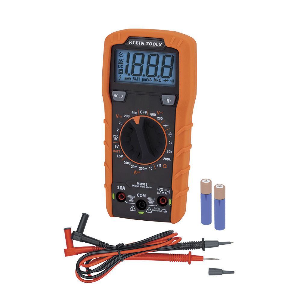
I have an MM325 voltmeter Klein brand, is this considered a high impedance testing unit and safe for this test? Just don’t want to mess up that ECU $$. I’ve posted the wiring diagram I’ve got. Is there any chance you can look at it and see if the “FL” connector is on there.

Thank you for the advice, I will try to get to it after work and post an update asap.
 

Attachments

  • Honda 50 wiring.pdf
    221.6 KB · Views: 2
Hi,
Yes, FFP is computer ground for the pump in that diagram. Hopefully you have the correct diagram.

Apologies...I was extrapolating the info from a larger outboard that is probably older as well.

This main relay is the simplest one I've seen.

Not sure if the ground is constant for the pump or is pulse width modulated (PWM) in this case or not. If it is, then it will be difficult to read the signal with a voltmeter. But, you could set to the millivolts scale and likely pick up the pulses.

You are wise to be cautious about testing the ECU.

While I know Klien is a decent name brand, I can't vouch for your meters impedence. But it's likely printed somewhere inside if you remove the back or battery cover. Otherwise it's probably posted on the web someplace if you search the model number.
You want 10 megaohms minimum to protect the components.
 
Here's the manual for your Klien MM325 meter:


Note that the impedence is listed at 2 megaohms

Here is an info sheet from Fluke meters that explains testing low current devices:


While your meter is probably ok to use to test the ground terminal of the ECU on this 10amp pump circuit, you might still need to be cautious about testing other functions using this meter.
 
Ok thank you, would testing the 12v positive at the fuel pump plug with a test light work as well? I don’t want to risk anything with the ECU if I don’t absolutely have to.
 
There's a very simple way to test this. Put a standard test light across the two teminals in the fuel pump plug( easy to do if you remove the intake manifold) and see if the light lights up for about 5 secs when you turn on the ignition. If it does then you need a new fuel pump. These engines do not have issues with main relays, keep it simple.
 
Not to be argumentative but I would NOT use a test lamp with an incandescent bulb in it for doing this. If you want to use a test light then use one with an led lamp ONLY (computer safe).

The "inrush current" of an incandescent light bulb can be quite high and could stress the computer circuit.
 
Jimmy, mate, I always test like this, a siezed fuel pump which this probably is and of which I've come across several, will draw way more current than a 10 watt light bulb.
 
thank you fellas , I wasn’t able to get to it today after work but I have taken the manifold off about 8 times already so I will check the output to the fuel pump plug with a test light “my test light has a lamp not a led” asap. I will also bench test the vst unit with 12v to see if it spins. That’s my plan at least. I will update with what I find.
 
Just my opinion but I would first check for battery voltage at fuse #7 (10a) with ignition switch on.

That verifies power to the Bu/R
wire that powers the pump.
If that's good then check that there is battery voltage at the pump connector with ignition on.

It was my understanding that you had already applied power externally to the pump and that the engine started and ran.

If that's the case, and the pump is getting voltage via the test I just outlined, then I think that the pump itself is likely "intermittent" and needs to be replaced.
 
On second thought, I should have said:
If the pump is getting voltage via the test I outlined and doesn't run...SOMETHING is intermittent. The pump? Maybe. But not necessarily the pump.

With the amount of YENOM (money spelled backards) they want for those, I would make dang sure it isn't something else before loading the parts cannon.

Like...
A loose connection someplace or a bad ground.

I would disassemble and thoroughly wire brush all grounds, including the battery cable connections. I have, over the years of my working on cars and trucks and outboards and equipment, been amazed at how often a simple bad ground can cause so much grief.

Finding a bad, loose or intermittent connection can be daunting too.

But there is a technique called voltage drop testing that can help immensely if you take the time to read up on it and apply the principles. Many, many good tutorials these days on the web and your meter will work well for doing that should you choose to try.

I was encouraged that you were able to jumper power to the pump and get the outboard running because voltage drops are always measured while the circuit is under load.

I know I'm probably driving Ian crazy right about now (and maybe you too) but, as he said before, I'm just wanting to do my best to help and this is just "my way".
Hoping to get to it later and I will try to see if power is getting to the fuel pump connection again. As you said I’ve already basically tested the pump by hardwiring it when running. Will double check that it’s running anyways. But it could still be at fault so I’ll keep an open mind. If I get 12v positive at the VST connection does that mean the pump is being triggered to turn on, or does it have more to do with the ground going to the ECU?

I guess I haven’t really understood how the power travels and what is supposed to happen when it’s working properly.

If the ECU was kicking the pump off because of high amp draw do you think it would at least spin up for a split second and then shut off, or would it be instant?
 
Hi,
I can only tell you what I see on your schematic.

Battery volts from starter terminal on white wire to fuse #7.(30a).
Fuse 7 feeds main relay.

With key ON, power from switch to main relay on the Bl/Y wire. That switches the relay and delivers power to the W/Bl wire that goes to the fuse panel.
The W/Bl wire changes color at the fuse panel and feeds the #2 fuse (10a) as the W/Bu wire.
That fuse then delivers power to the pump via the Bu/R wire.

If the pump gets power at the VST connector then all that's left is for the ECU to ground the Bl/W wire from the VST connector at the FFP terminal.

By jumpering power to the pump and running the engine, you have already proven that the ECU will and does ground that wire.
Well....
At least it did at that time.
 
ok I tested the connector at vst and with the key on it is constantly hot as well when you go turn to crank. I guess that is always constant and the ecu chooses when to ground the pump completing the circuit? Also jumped the pump to make sure it’s still operating and it is.

When we jumpered the fuel pump we put wires to both the pos. and neg. terminals on the vst with the harness plug disconnected. Was there another way? I guess we bypassed the ecu by doing that…

Maybe I’m in over my head on understanding exactly how the ecu is controlling the main relay.
 
The main relay is working. You just proved that when you got voltage to the pump when you turned the key on.
The main relays only job on this outboard is to power the number 2,3 4,5 and 6 fuses in the fuse box.
It's all there in wiring diagram.
 
Yes...when you provided BOTH ground and power to the pump, you indeed bypassed the computer pump control circuit.

So it comes down to this....
With everything hooked up normally...

When you turn the key from OFF to start, is there 0.00v measured at the FFP terminal on the ECU and does it rise to battery voltage after 3 to 5 seconds?

Voltmeter red lead to FFP terminal and black lead to a good ground.
 
If you have the intake off you can hook your meter up like Ian described doing with a test light. Then when you turn the switch on, the meter should read voltage as it gets a ground and go to zero volts after 3 to 5 seconds.
 
Ok I must of overlooked or misread what Ian had posted and will definitely begin with that test tomorrow, Ty for pointing that out jgmo. I was using the main ground when testing that, but using the ground that goes to the ecu makes sense now.

Following that if needed I will also perform the test you suggested. It’s starting to make more sense the more I read what you guys are posting. I’m just hesitant sometimes to go probing on things because of not understanding actually what’s happening. I appreciate everyone’s input thank you very much.

Will again update after work tomorrow.
 
Back
Top