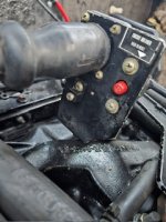
I’m looking for a little help with my 1977 Sea Ray 240 Weekender. I have changed the trim sender switches on the outdrive the limit switch was self explanatory . The position switch on the other hand is a little bit more challenging, the wires from the position switch go to this block below the harness I assume. There are no other wires to those terminals to be found. The gauge has the purple/white wire and the black wire on it but they are cut off and I don’t know how to reconnect them . Can someone help me out with this question . Thanks for now .
Home
Outboard Motor Parts
Chrysler outboard parts Evinrude outboard parts Force outboard parts Honda outboard parts Johnson outboard parts Mariner outboard parts Mercury outboard parts Suzuki outboard parts Tohatsu outboard parts Yamaha outboard partsInboard & Sterndrive Engine Parts
Chrysler Marine inboard parts Crusader Marine parts MerCruiser sterndrive parts OMC sterndrive parts Pleasurecraft Marine parts Volvo Penta marine parts + MoreAll Engine Brands
All Manuals HomeOutboard Repair Manuals
Chrysler outboard manuals Evinrude outboard manuals Force outboard manuals Honda outboard manuals Johnson outboard manuals Mariner outboard manualsMercury outboard manuals Nissan outboard manuals Suzuki outboard manuals Tohatsu outboard manuals Yamaha outboard manuals
Inboard & Sterndrive Engine Manuals
MerCruiser sterndrive manuals OMC sterndrive manuals Volvo Penta marine engine manualsPlease Note
MarineEngine.com does not offer troubleshooting assistance or repair advice by email or by telephone.
You are invited to join our public Boat Repair Forum to seek assistance from other members.
You may also visit the Boat Motor Manuals section of our site to obtain a service manual.