Logo

Where should I cut for motor mount

Figure9

Member
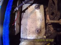
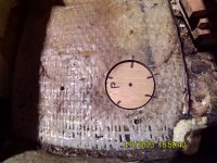
I'm working on a 1985 Rinker v170 with mercruiser 3.0 and have an issue with the front 2 lag bolts are rusted and not biting into anything solid. I need to cut into the motor mount platform, but not sure where. Here is a pic of what my plan to do unless I am told otherwise by someone who knows better. See red square.
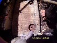
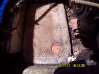
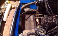
Also, was it standard practice to put expanding foam underneath the motor mount pad, or was this done by someone else.?
 

Attachments

  • Cutout.JPG
    Cutout.JPG
    317.4 KB · Views: 11
Last edited:
not exactly sure what you plan is based on your post....

if the mounting pad is solid, I'd leave it in place and cut some hole 'in front' of the mount's holes to add a washer and a locknut to secure the mount's bolts.

If the pad is not solid, you'll have to replace it...it needs to be solid enough to hole the engine in place to maintain the engine's alignment relative to the gimbal bearing.

On the foam, back in the 80's there were those that used foam and those that didn't and lots of changes. For the little bit of volume under the front mounting pad, it won't make any difference. if you do use any foam, make sure it is a 'closed cell' type so it doesn't absorb any water...
 
not exactly sure what you plan is based on your post.... if the mounting pad is solid, I'd leave it in place and cut some hole 'in front' of the mount's holes to add a washer and a locknut to secure the mount's bolts. If the pad is not solid, you'll have to replace it...it needs to be solid enough to hole the engine in place to maintain the engine's alignment relative to the gimbal bearing. On the foam, back in the 80's there were those that used foam and those that didn't and lots of changes. For the little bit of volume under the front mounting pad, it won't make any difference. if you do use any foam, make sure it is a 'closed cell' type so it doesn't absorb any water...
I wasn't sure how the pad was constructed and I didn't want to cut out more than I had to. Yesterday, using a 3" hole saw, I cut out around the mounting holes. It isn't as bad as I thought, so I'm going to soak it with cpes then fill the voids with epoxy. About an inch below the mounting pad, it looks like another layer of fiberglass, then below that is void. It looks like the previous owner used expanding foam to fill that area under the pad to keep bilge water out, but all it did is soak up the water.
 

Attachments

  • Screenshot 2022-12-28 180920.jpg
    Screenshot 2022-12-28 180920.jpg
    86.3 KB · Views: 5
I wasn't sure how the pad was constructed and I didn't want to cut out more than I had to. Yesterday, using a 3" hole saw, I cut out around the mounting holes. It isn't as bad as I thought, so I'm going to soak it with cpes then fill the voids with epoxy. About an inch below the mounting pad, it looks like another layer of fiberglass, then below that is void. It looks like the previous owner used expanding foam to fill that area under the pad to keep bilge water out, but all it did is soak up the water.

Ayuh,...... That oughta work, just fine,....

Don't forget to realign the motor, after ya get it all back together,.....
 
Couple pictures of the mounting pucks. I drilled a few holes around the perimeter of the puck and matching holes in the mounting plate so that the epoxy will flow into to lock it in.
 

Attachments

  • FHD0128.jpg
    FHD0128.jpg
    255.9 KB · Views: 1
  • FHD0131.jpg
    FHD0131.jpg
    253.1 KB · Views: 4
  • FHD0133.jpg
    FHD0133.jpg
    222.5 KB · Views: 1
  • FHD0134.jpg
    FHD0134.jpg
    323.2 KB · Views: 3
Back
Top