Logo

volvo 290 drive

jmo

New member
I am new to boating, just had my volvo 290 single prop drive pulled and in for service. I noticed a whirling sound from the fly wheel area when the engine is running. The pds has some up and down play in it.
Is my bearing(s) in need of replacing. And just to check if the noise is in deed the bearings, can i pull out the pds and run the engine with out doing any harm to see it the noise goes away. Thanks maybe its not a 290 it has black paint over it
 
..............

Me in blue text.

I am new to boating, just had my volvo 290 single prop drive pulled and in for service. I noticed a whirling sound from the fly wheel area when the engine is running. The pds has some up and down play in it.
Is my bearing(s) in need of replacing.
If you can notice up/down play or slop in your PDS, the Yes...... you are way over-due for bearing replacement.


And just to check if the noise is in deed the bearings, can i pull out the pds
During the 290 drive run, Volvo Penta was still using the double bearing PDS in the Red 1 pc GM V-8 flywheel cover (bell housing in the auto world)
Great system if the owner kept up on greasing the PDS bearings.
Bad news is...... with the double bearing PDS, the engine must be removed in order to change the two bearings.
Bad news #2, if you do not replace these bearings, the resulting damage can be catastrophic.

and run the engine with out doing any harm to see it the noise goes away.
A waste of time if you are able to feel play or slop here.
Bite the bullet, and replace them.


Thanks maybe its not a 290 it has black paint over it
AQ series Volvo Penta drives are Aquamatic Green or the light gray color.
Could be black anti-fouling paint for aluminum out drives.
Make darn sure that it isn't conductive bottom paint.
 

Attachments

  • flywheel cover grease hose.jpg
    flywheel cover grease hose.jpg
    23.1 KB · Views: 309
  • PDS coupler and drive shaft 2.jpg
    PDS coupler and drive shaft 2.jpg
    49.8 KB · Views: 2,694
  • Broken Flywheel Cover explosion.jpg
    Broken Flywheel Cover explosion.jpg
    8.2 KB · Views: 1,843
Last edited:
having trouble uploading pix the bell housing is red and it looks like 1 piece there is a grease fitting near the steering on the grey round housing in which the bell housing looks like sits in. sorry im new to boating. 20131004_072855.jpg20131004_072931.jpg
 
That is an early 280 drive. The 290 offers hydraulic tilt/trim.

I'd suggest that you separate the engine from the flywheel cover, and remove it from the hull.
Pull the stringer lag bolts, and leave the mounts attached to the engine so that you don't upset the engine mount height adjustment.
Replace the PDS bearings/seals while the F/C is still in the transom shield.


If you should decide to pull the engine with the flywheel cover attached, I'd strongly suggest that you replace at least the inboard large rubber cushion ring.
The inboard cushion ring provides the water seal, and these typically won't seal correctly second time around.


BTW, these are industry standard bearings and seals. No need to purchase through Volvo Penta.


Also, it this black paint is conductive bottom paint, there should be at least a 1" clear area (non-painted) around any metallic components.
Otherwise, it will bring your drive components into the electrical path..... (I.E., accelerated galvanic corrosion).

attachment.php


.
 
Last edited:
im trying to isolate the noise i hear that it is 100% the pds bearings and not anything else. did u see the 2 pix sorry they are sideways. 20131004_075107.jpgjust to verify is this a 290
 
can i just pull out the pds and run the engine to see if there is any other noise.
Yes, once you have the engine out of the boat, you can remove the PDS from the flywheel cover.
You'd then need to start and run the engine on blocks or an engine stand.

But as said earlier, the double bearing PDS will not allow for removal until the engine is removed.
With the engine removed and out of your way, you'll have access to the FWD bearing, seal and snap ring....... otherwise you will NOT.


The OHC 4's, and the later V-8 flywheel covers use a single bearing PDS with a pilot nose and crankshaft bushing.
These are removable from AFT without removing the engine.


BTW, this is a 280 drive with a 290 lower unit.
The dead give-a-way, is the exhaust outlet flapper.
Only a limited quantity of the 280 production models had the flapper, and the 280 flapper is considerably different from the 290 flapper.

Pay no attention to this. It will not change anything regarding lower unit parts, seals, work scope, etc.

attachment.php


Bottom line...... you have no choice but to replace these bearings/seals.
I can guarantee you that these will fail, and if you're lucky, the failure will only take out the flywheel cover bellows snout.
A good used GM V-8 flywheel cover will run you about $400.
Then you'll want to install new bearings/seals.

If you're not so lucky, it will also take out the universal drive shaft (or parts of it) ....... and in extreme cases, the front clamping collar of the transmission.

A good universal shaft will run you about $400+.
A new clamping collar runs about $380.
The labor to correctly install the new universal shaft and the new clamping collar will run you about $450-550 or so.


.
 
Last edited:
ok it also seems to be converted to fwc. the inlet hose under the shifer cable the clamp cut the drive bellows which probably caused all this water intrusion. how do i completey remove the hose and seal up the water outlet port on the drive and the hole that brings the ocean water in thru the back wall.
 
ok it also seems to be converted to fwc. the inlet hose under the shifer cable the clamp cut the drive bellows which probably caused all this water intrusion. how do i completey remove the hose and seal up the water outlet port on the drive and the hole that brings the ocean water in thru the back wall.
I'm not following you at all.

You do not want to change from the OEM system. It works flawlessly when everything is up to snuff.


.
 
The larger S shaped hose is called the "S" hose. It is a collapse proof suction hose.
They will become stiff occasionally, and do need to be replaced once in a while.
The aluminum fitting that the "S" hose attaches to at the drive side, is the "water neck" fitting, and these routinely require replacement.

The two bent elbows are "rubber hooks". These direct low RPM exhaust gasses out towards the sides...... I.E, exhaust relief ports.
In order to replace these, the exhaust Y-pipe must be removed.
Unless they are leaking water into the hull, I'd leave them alone.
However, since you'll have the engine out, this would be a good opportunity to replace them.


BTW, all of these band clamp "worm drive screws" must be strategically positioned, or you will risk interference that may cut or damage the rubber components.

Drive shaft bellows require routine replacement.
The exhaust bellows will go for years without replacement.
And BTW, your exhaust bellows are not fitted with the internal flappers.... and this is correct.
You DO NOT want the internal flappers when there is a flapper on the drive outlet.


Take your time.... examine each component.... do a Pressure/Vacuum leak-down test on the drive..... replace what's necessary..... and you'll have a good stern drive system that will last for many more years.


BTW..... when you reinstall the drive, install the main suspension fork and intermediate housing as one unit.
The lower unit can be attached as well.

Hold off on installing the transmission until last.

This frees up the upper area for easier shift cable attachment, easier water neck fitting "S" hose connection, and easier transmission fit and bellows connection, etc.
Do this, and you won't be fighting the drive and the other things simultaneously.


.
 
Last edited:
my boat is a fresh water cooled system. the s hose has been plugged up inside the engine compartment. id like to do away with the s hose completely,any suggestions.
 
also the grease fitting on the f/c is that the pds bearing grease point. and when i replace the bearings are they supposed to be sealed or not. not sure what i should get. ?? thanks
 
my boat is a fresh water cooled system. the s hose has been plugged up inside the engine compartment. id like to do away with the s hose completely,any suggestions.
The "S"hose is at the exterior of the transom shield.
The large suction hose from the chrome water tube to the crankshaft pump is within the engine compartment.

My suggestion would be to correct any bad or worn parts, and use the OEM system.
Whether your engine is fitted with a Closed Cooling System, or a Raw Water cooling system, this portion of the cooling system is identical.


also the grease fitting on the f/c is that the pds bearing grease point. and when i replace the bearings are they supposed to be sealed or not. not sure what i should get. ?? thanks
Since there is a grease fitting that ports into the bearing cavity, these bearings must be "open", as a sealed bearing will not accept grease.
The bearing p/n's are right here.
The two seals are in a TCM or Timken brand 35x62x7mm
Install seals only after the new bearings and grease cavity have been "Pre-filled".
The AFT seal installs in a non-conventional direction.
FWD seal should be glued in place.


attachment.php
 
once i unbolt the f/c and all wires and lines and lag bolts the engine should lift straight up or does it need to shift back a little, does it need to be completely removed or can the engine be shifted forward to do the bearings. how do i get the bearings out are there any retaining rings, ect
 
once i unbolt the f/c and all wires and lines and lag bolts the engine should lift straight up or does it need to shift back a little,
The engine will need to slide forward, not rearward, before the PDS will disengage from the Borg Warner drive coupler splines.
Only then can it lifted up and out.


does it need to be completely removed or can the engine be shifted forward to do the bearings.
That's your call.
There are many things that can be looked and/or addressed with the engine completely out of your way.


how do i get the bearings out are there any retaining rings, ect
You'll need to purchase an OEM work shop manual. Not Seloc... not Clymers.

Do a forum search for Volvo Penta PDS bearing replacement.
We've discussed this topic many times here.


You'll need to modify a long needle nose pliers in order to grab onto the deeply set snap ring eyelets.
The tips will be ground down some and will be tweaked inwards a bit.
I've never found a conventional snap ring pliers that works as well.

The PDS exits from AFT.... and only after the two AFT snap rings have been removed.
It will come out with the 6206 bearing still attached to it.
The 6007 bearing will remain in the flywheel cover until after the PDS removal.
 

Attachments

  • PDS coupler and drive shaft 3.jpg
    PDS coupler and drive shaft 3.jpg
    68.2 KB · Views: 289
  • PDS coupler and drive shaft 4.jpg
    PDS coupler and drive shaft 4.jpg
    47.5 KB · Views: 199
  • PDS grease cavity location.jpg
    PDS grease cavity location.jpg
    21.1 KB · Views: 327
  • Long needle nose pliers.jpg
    Long needle nose pliers.jpg
    5.4 KB · Views: 156
Last edited:
Here's what your new bearings and seals will look like.
Steer clear of the Chinese bearings.
Go with German, USA, Japanese, or anything but Chinese.

ball-bearing-6206_medium601B6206-01_c535.jpg


51gNGsi3a%2BL._SL500_AA300_.jpg


35X62X7mm seal (X's 2) in a TCM or Timken brand.
(TCM or Timken will be fully rubber encapsulated)

50286_pic2.jpg


If you have any buying power and/or if you go directly to a Major Bearing supplier, you can purchase all of these parts for around $45 or so.

These typically do not go bad, but if you should need to replace a snap ring, these are nothing special.
NAPA or any good parts store should have them. Just take your old one in with you.
There will be 3 of the larger snap rings, and only 1 small.
1-250x250.jpg


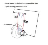
KEY WORDS: Pre-fill the grease cavity while spinning the PDS prior to installing the seals.

Use a good high pressure bearing grease... not the green Marine wheel bearing grease.
Stay with the same grease in the future as you lube these... in other words...... DO NOT mix grease chemistry.

*******************************

BTW, if you replace the transmission universal drive shaft bearing crosses, these are a Spicer 5-1306X.
Same exact replacement part.... US quality..... and at a fraction of what Volvo Penta wants for their replacement part.


*******************************************

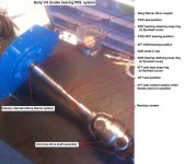
Here are a few photos of what your flywheel cover and PDS will look when taken apart.

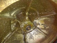
First image shows a FWD seal that was not installed correctly, and was blown out of position by grease pressure.
This could have been caused from not gluing the seal........ or it could have been caused by the AFT seal not having been installed correctly.

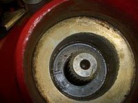
Second image shows the FWD seal installed correctly. This is also the Borg Warner spline end of the PDS.

Third image shows the AFT PDS seal installed incorrectly. (this is a fine spline PDS.... yours may be course spline)
Note that the seal's lip and tension spring should be visible. (this one is reversed)

Forth image shows the location of the two AFT-most snaps rings that must be removed in order for the PDS to be removed in the AFT direction.

Last image shows a bare PDS.
This one is fine spline at the female yoke end.... yours may be course spline.
The Borg Warner end is the same regardless.
 

Attachments

  • coupling1.jpg
    coupling1.jpg
    68 KB · Views: 137
  • PDS AFT seal incorrect install.jpg
    PDS AFT seal incorrect install.jpg
    15 KB · Views: 158
  • PDS FWD seal correct install.jpg
    PDS FWD seal correct install.jpg
    8.9 KB · Views: 143
  • PDS snap ring location.jpg
    PDS snap ring location.jpg
    56.2 KB · Views: 191
  • Primary Drive Shaft AQ 260.jpg
    Primary Drive Shaft AQ 260.jpg
    1.9 KB · Views: 1,638
Last edited:
my boat is a fresh water cooled system. the s hose has been plugged up inside the engine compartment. id like to do away with the s hose completely,any suggestions.

FWC and the "S" hose are not related. You can have FWC or RWC and bring the cooling water in thru the drive via the "S" hose or plug the hose for either system an bring water in thru the hull as I did. See pix. below. I changed the external filter scoop on the hull this season to one with a removeable strainer face.
Plumbing inside as shown allows for fresh water flush without muffs for easy flushing or winterizing. To do this use a short hose to a 5 gal pail with a garden hose running free into the pail. DO NOT HOOK THE FLOWING GARDEN HOSE DIRECTLY TO THE FLUSH PORT ON THIS SYSTEM.
 

Attachments

  • ThruHull_rawwaterinlet_internal_2266.jpg
    ThruHull_rawwaterinlet_internal_2266.jpg
    62.1 KB · Views: 146
  • Thru_Hull_WaterInlet_2257.jpg
    Thru_Hull_WaterInlet_2257.jpg
    64.2 KB · Views: 127
Last edited:
  1. FWC and the "S" hose are not related.
  2. You can have FWC or RWC and bring the cooling water in thru the drive via the "S" hose or plug the hose for either system an bring water in thru the hull as I did.
  3. Plumbing inside as shown allows for fresh water flush without muffs for easy flushing or winterizing. To do this use a short hose to a 5 gal pail with a garden hose running free into the pail.
  1. How so?
    Either a Raw Water Cooling system, or a Closed Cooling system uses the "S" hose when the system is OEM.

  2. Agreed.

  3. Use caution if you plan to winterize a RW cooled engine via this method.
    See this write up.
    Dang near every Spring time some poor unsuspecting person ends up with a cracked block or heads because they used this method, and did not fully understand the pitfalls.
 
Back
Top