Logo

volvo 275

guppy

Regular Contributor
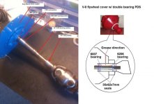
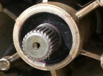
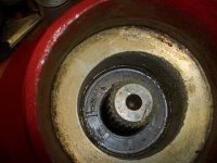
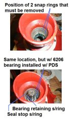
Does anyone know if there is a seal saver,aka redi sleeve, available for the coupler to pds? Mine has some pitting and a groove worn from the seal. Have used them successfully many times on harmonic balancers and spindles. Don't really want to replace that coupler if it can be repaired. Any suggestions or input would be appreciated. Thanks in advance. ps mine is a fine spline v8 coupler.
 
This is not intended to be a water tight seal. Don't worry about it!

Just make sure that the FWD PDS seal is installed in the "conventional" direction, and is glued or staked in place!
Make sure that the AFT seal is installed in the "non-conventional" direction.

.
 
Last edited:
Update to my last post. (that was via my iPhone)

The female yoke that you are talking about, has a dust cap at the AFT end of it.
These dust caps are not water tight to begin with.
If the seal and yoke seal surface were "perfect", and if your drive shaft bellows was to leak water, the dust cap will be your weak link anyway.
And even if that was to occur, you'll be having a much larger issue!


The reason for gluing the FWD seal in place is to prevent future "over" grease gun pressure/volume from dislodging it.
If we loose the FWD seal, the AFT bearing may never see any future grease. The AFT bearing is the more critical bearing.

Here's how the FWD seal will look when installed.
The tension spring and seal lip will face the PDS grease cavity.
1048_1.jpg


The reason for the AFT seal being installed in the Non-Conventional direction, is to make certain that is does not hold hydraulically.
IOW, we want this seal to breach any excessive grease gun pressure/volume.

Here's how the AFT seal will look when installed.
The tension spring and seal lip will be visible.
50286_pic2.jpg


If installed in the conventional direction, it will tend to hold hydraulically (that's how a single lip seal is intended to function).


.
 
Last edited:
Rick, thanks for the reply, gives me new inspiration to finish my boat. Now I can get back on track with knowledge that it's not gonna cost lots of extra $.
 
I like to follow along on these discussions and learn something if possible, but I can't figure this one out. What and where is the "coupler to PDS"? I know what the PDS is, but can't find anything called a coupler on the schematics.

I can be as slow as last weeks molasses, so will somebody take pity on me and orient me as to what a "coupler is"? Thanks.
 
I thought the coupler/asorber was on the fly wheel and the PDS is the primary dive shaft that goes through the bell housing??
How about some pics?
 
I thought the coupler/asorber was on the fly wheel and the PDS is the primary dive shaft that goes through the bell housing??
How about some pics?
Your wish is my command, Jerry!

First image shows us the Borg Warner drive coupler and PDS along with the bearing/seal locations, and how the PDS sits withing the Flywheel Cover.
Second image shows the B/W end of the PDS. (B/W is B/W is B/W all day long)
Third image shows the transmission's universal drive shaft end of the PDS.... (fine spline shown)
Forth image shows the snap ring locations...... (course spline shown)
Fifth image shows us a bare bones double bearing PDS.

On a scale of 1 to 100, how'd I do? ;)
 

Attachments

  • Primary Drive Shaft AQ 260.jpg
    Primary Drive Shaft AQ 260.jpg
    1.9 KB · Views: 124
  • PDS coupler and drive shaft 4.jpg
    PDS coupler and drive shaft 4.jpg
    47.5 KB · Views: 81
  • PDS FWD seal correct install.jpg
    PDS FWD seal correct install.jpg
    8.9 KB · Views: 71
  • PDS AFT seal incorrect install.jpg
    PDS AFT seal incorrect install.jpg
    15 KB · Views: 77
  • PDS snap ring location.jpg
    PDS snap ring location.jpg
    56.2 KB · Views: 85
Last edited:
Back
Top