Logo

Timing on a 94 4.3 lx

duckhunter185

Contributing Member
Getting ready to set the timing on my 4.3. I've read on here many times that you set the #1 cylinder at 10 degrees btdc. This engine came out of a truck. Do i still set timing at 10 degrees btdc. If so why is it set 10 degrees below? When I've timed chevy engines in the past I've set #1 at top dead center and been good. Thanks!
 
This question is tricky. Your engine will need the final timing on the water and you will have to essentially go old school and " set it by ear ".

The above is only my opinion... want me to delve deeper into my reply i will. Your engine needs to be set where it likes it the best.

My 85' 3.0l / 140 " says 140 right on the valve cover " has to be " set by ear " on the water also, it doesn't like where the book says it should be.
 
The engine calls for 8 btdc. Does it have a timing tab on the cover? or does it have a plastic timing cover with a notch?
 
Getting ready to set the timing on my 4.3. I've read on here many times that you set the #1 cylinder at 10 degrees btdc. This engine came out of a truck. Do i still set timing at 10 degrees btdc. If so why is it set 10 degrees below? When I've timed chevy engines in the past I've set #1 at top dead center and been good. Thanks!
BTDC = Before Top Dead Center!
That may be where you are confused.

In order to create LPCP at/near 12*-14* ATDC, ignition occurs before TDC.

See the OEM ignition timing specs for this engine in a Marine application.... NOT an automotive application.


This question is tricky. Your engine will need the final timing on the water and you will have to essentially go old school and " set it by ear ".
I would strongly advise against doing this!

No offense to you, MM........ but I know of no polite or gentle way to have said that, and yet get the point across.

Again, see your OEM specs for the correct progressive ignition advance, and see the limit RPM where advance is "Full-In" and stick with those numbers.
Otherwise, you'll risk ignition induced detonation damage, ranging anywhere from this.........

piston_detonate1.gif


...... to this.

images


.
 
Last edited:
Thanks for all the replies! I haven't yet been able to locate the timing notch on the timing cover. I'm use to it being on the front right side of the engine. I can get the engine to TDC. Just Hope there is still a "notch" and it hasn't broken off. I'm pretty sure TDC will get me close enough to were I tweek it in. Agree? Or any other ideas if I don't have the timing notch.... Thanks again!
 
Rick has one of the finest mechanical minds on this planet, i never take offense. If the truck engine does not have the internals of a marine engine, how you going to use marine engine specs ?

I can give suggestions, it's up to the owner to do what he wants. What i would do is take all the advice i can get disregard dummy's like me and keep in mind it's your boat.
 
Rick has one of the finest mechanical minds on this planet, i never take offense.

If the truck engine does not have the internals of a marine engine, how you going to use marine engine specs ?
MM, first.... thank you.
Secondly..... you're not a dummy for having suggested that.

All I meant by my comment was to caution anyone from setting Marine Engine ignition timing by ear. We may be only a few degrees away from causing detonation. That is the risk, IMO.

As for the truck engine internals, I don't have the same issues with the cam profile, per se', as I would with combustion chamber design.
GM loves the full dished pistons, whether Marine or Auto.
However, when I do a search re; the 4.3L, I come up with both Full Dished and F/T's. It would be helpful to know which pistons were used.
images
1482Ha.jpg


The full dished pistons offer very little in the way of preventing detonation...... in fact, this piston actually promotes detonation if we aren't conservative re; ignition advance.
So, whether Marine or Auto built, I'd use the Marine timing specs for this engine in a Marine application, and avoid the risk of detonation damage.


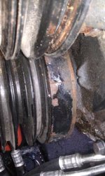
duckhunter185, there must be a TDC mark somewhere at the front of this engine. It may be a single pointer.... I don't know.
Can you post photos?

.
 
One more note:
If this has thunderbolt V then there is a wire lead that needs to be shorted to ground when doing base timing. It takes out the knock sensor from influencing the base timing. If it has a newer ignition (mercriuser) it still may need a wire either jumped or grounded. You need to identify the ignition.
 
Ive got thunderbolt iv ignition.
timingmarknew1.jpgOnly timing mark i have is TDC as you can see in the picture.....
 

Attachments

  • timingmarknew.jpg
    timingmarknew.jpg
    21 KB · Views: 1,028
Last edited:
plastic cover, the notch is tdc buy yourself an advance digital timing light and install timing tape on the balancer. I just did this on my 4.3 came out at 8 BTDC... You have a frankenstein engine block is truck, manifolds,riser,hopefully starter, alternator, ignition are marine...
 
Last edited:
Thanks for the help! Yep it has all been swapped marine. Even got the good quicksilver manifold and riser exhaust gaskets. I've never used an advanced digital timing light or timing tape. What is different from a plain ol' timing light? And how do you use the tape
 
Measure your balancer the (pulley with the mark on it) I think it's 6 3/4" dia. go to summit racing.com or E-bay.com there you can buy the timing tape ($6-8.00) with instructions on how to apply it to the balancer, use your plain ol' timing light to time the engine you should be close to 8 btdc. This is the easy way A good digital timing light goes for about $125.00-150.00 bucks good luck :rolleyes:
 
........... What is different from a plain ol' timing light? And how do you use the tape?
Unless you own a High End digitally advancing timing light, I'd mark off your balancer up to approx 35*.
With the known diameter of the balancer, you can buy a degree decal specific for that diameter.
Clean the balancer, and apply the decal zero-to-zero, and towards Port of the TDC mark.

Now you can time the ignition using the standard light (or standard mode), and see your ignition advance in Real Time/Real Degrees.

This removes the liklihood of user error or equipment error.

.
 
Very nice thanks everyone! Do I need to know the size of the balancer to get the correct tape or can I just buy some? Also when you say mark it up to 35* you mean by the marks on the tape? Thanks again you are all a big help!
 
  1. Do I need to know the size of the balancer to get the correct tape or can I just buy some?
  2. Also when you say mark it up to 35* you mean by the marks on the tape?


  1. The diameter of the balancer determines the distance between degree markings at the circumference. If the diameter changes, the circumference changes, then so does the distance between degree markings. So yes......... you need to know the diameter.
  2. If hand marking off the balancer, take it up to 30* or 35* or so just for reference. I think that the decals go to 40 or 45 for HP Auto use.
 
You can also mark off the balancer using geometry of like diameters.
Here's a copy/paste from info that I just recently posted on another marine forum:

Find the OD of your balancer.
Draw an identical diameter circle on paper (we need to be using the same circumference dimension).
Using a degree wheel, divide this circle into a 30* wedge section....... or take it further, and divide it into increments of 5* up to 30* at the circumfrence.
Using an old school architect's compass, set the compress between the Zeor mark and the new 30* mark on your paper circle.
Lock the compress down.
Transfer this over to the balancer, beginning with one pointer in the TDC notch.
Scratch the new 30* mark towards Port from the TDC notch (std LH rotation engines only).
Make this 30* mark a bold one.

Now go back and set the compress for 5*, and again, sratch a new 5* mark towards Port, beginning with one pointer in the TDC notch.
Repeat this for 10*, 15*, 20*, 25* and so on, each beginning at the TDC notch.

attachment.php


attachment.php
 
Last edited:
Back
Top