Logo

Tilt/Trim Sender Signal

grothm01

New member
How can I test the "sender" signal on the tilt & trim of my 1987 Johnson
90 HP outboard? My gauge is broken and I bought a new gauge but it doesn't work. I want
to be sure it is the gauge and not the "sender" signal that is causing the
problem.
 
To test the gauge, simply have voltage applied to it in a normal fashion and then run a small jumper wire from the "S" terminal to the "G" terminal. If that causes the needle to pin itself, the gauge is okay.

To test the sender, have the sender wires disconnected and connect a ohm meter between the two wires. Now, slowly move the sender's action arm from one extreme to the other. The meter needle should move constant and smoothly from one direction to the other....... NO jerks, dead spots, etc!
 
To test the gauge, simply have voltage applied to it in a normal fashion and then run a small jumper wire from the "S" terminal to the "G" terminal. If that causes the needle to pin itself, the gauge is okay.

To test the sender, have the sender wires disconnected and connect a ohm meter between the two wires. Now, slowly move the sender's action arm from one extreme to the other. The meter needle should move constant and smoothly from one direction to the other....... NO jerks, dead spots, etc!

Thanks for the information. I haven't had a chance to work on it yet. I have since got a replacement gauge and maybe you can help me with a question. It has a jumper between the "I" & "S" terminals. My original gauge didn't have this. Is this possibly something left on from testing?
 
Hopefully not a jumper wire but rather a resistor... and if a resistor, yes, it belongs there, it's a needed component.
 
Hopefully not a jumper wire but rather a resistor... and if a resistor, yes, it belongs there, it's a needed component.

OK. The sender checked out. I hooked the replacement gauge up and it show "UP" when motor is down & "Down" when the motor is up. What could be causing that.
 
Follow the wires back to its plastic/nylon connector and switch them there. Think about it..... those two wires have got to connect to something somewhere.
 
Follow the wires back to its plastic/nylon connector and switch them there. Think about it..... those two wires have got to connect to something somewhere.

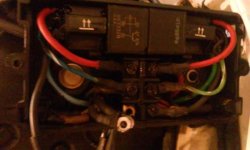
Now I'm really confused. I followed the two wires to this wiring block (attached photo). Both wires were connected to the same post (see disconnected wires).

Wiring Block.jpg
 
Now I'm really confused. I followed the two wires to this wiring block (attached photo). Both wires were connected to the same post

Yeah, me too if that's actually the two wires leading from the sending unit. Is it possible you got sidetracked at some crowded area and got switched to different wiring?

It's impossible to get a UP reading and also a DOWN reading with the sender wires hooked together.

That unit is the PTT relay and terminal block "Junction Box" (blue wiring=up...green wiring=down). I would suspect the one of those wires is indeed going to the sending unit BUT the other wire would be at the same level on the opposite side of that terminal block.

However, at any rate... inside that Junction Box IS NOT the place to do any switching.

The normal wiring of the sender is two wires leading from the electric motor to a nylon coupler assembly that simply unplugs.
 
Last edited:
Back
Top