Hi Guys,
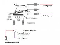
I posted this question a while ago with no response, going to try again. The engine is a 1986 4.3 with electric fuel pump. The pump is being power by a red pig tail that is spliced into the red wire. The pump is not tied into the oil pressure switch but will be in time. The engine cranks strong but only getting 6 volts from this red wire. It has run in the passed with this wireing set up. Could someone tell me what would cause the red wire to only have 6 volts? And where does this wire get its full 12 volts from. Thanks for any help given.
I posted this question a while ago with no response, going to try again. The engine is a 1986 4.3 with electric fuel pump. The pump is being power by a red pig tail that is spliced into the red wire. The pump is not tied into the oil pressure switch but will be in time. The engine cranks strong but only getting 6 volts from this red wire. It has run in the passed with this wireing set up. Could someone tell me what would cause the red wire to only have 6 volts? And where does this wire get its full 12 volts from. Thanks for any help given.