Logo

Props for pre 1994 270aqT outdrive

Mujibar

Member
I have acquired a 22.5' custom built 1975 cuddy "cruiser"?. It has not been in the water for at least 12 years. It is powered by a 351w engine. It has a 270aqT, (I think, plate says 270T) outdrive.

I just spent the day turning a prop and its hub into aluminum paperweights. The years of encrusted salt and corrosion were impervious to liquid wrench, penetrating oil, Wd40, heat and a puller. When I took what was left to a highly reputable prop shop in Ft. Lauderdale, they pointed to a list of discontinued props for all AQ models.

Additionally, there were no identifying #'s or marks, which would provide a hint as to what the original prop was. A tape measure quessing game ensued, as to diameter and pitch.

Perhaps someone, (without belabouring what I have done wrong so far) can lead this poor old man from the wilderness I am in, and point out a better course?

Am I expected to pay exorbitant VP prices for VP props for these models?

Will other props fit? Do I need special hubs?

Oh! In addition, when I removed the keeper cone, It had a helicoil thread insert. What do I need to do about that?

New shaft, or probably just a new cone, if available?

Thank you for any help that may be forthcoming,
Jerry
 
Jerry, it's possible that a T drive rear cover has been installed on a std 270 drive.
Post a few photos of it for us.

The T drive was short lived. You'll be hard pressed to find any of the rubber components that you will need for this drive.
If it's a T...... I'd cut your losses and replace the transom shield with another like vintage Volvo Penta drive.
You can use the 270 transmission and lower unit.
 
Well there is an answer I was not expecting. Having read all 32 pages of the forum, rarity is a surprise. Although,the 270AQ T along with the AQ240 (351w) engine are hardly ever asked about.

Your extensive knowledge has been noted, and I am happy you were willing to respond to my questions.

O.K. so it seems first I will need to replace my broken digital camera.

But? What are the rubber components you speak of? except for the bellows and S hose, the only rubber encountered is that between the prop hub and prop?

How does replacing the shield assembly, (still working) and keeping the lower part of the 270 solve my problem of aftermarket prop availability for AQ drives?

I suppose I will have to spend my declining years, caroming my mobility scooter up and down aisles of used parts warehouses and flea markets.

Assuming I change the whole sterndrive to a later model. What would you reccomend as an inexpensive (Relatively) alternative to what I have now.

Jerry
 
Jerry, first verify that it is indeed a "T" drive. Post a few photos for me, and I can tell you what you have.

The 270 is a good and quite common drive, along with the 5.8L Ford. Nothing wrong with either. The issue is the T drive and it's hydraulic trim system and the rubber
components necessary to keep one up to snuff. These parts are no longer available, and I can almost guarantee you that they are in need of replacement... if not now, soon.

Again... nothing wrong at all with the engine and drive itself. Parts are available. Used parts are reasonably priced due to supply/demand. These don't wear out, so the demand is relatively low compared to XYZ and ZYX drives.
 
Definitely the 270T as in your diagram. I went by today and checked to make sure. The lift operating motor underneath is the big giveaway.

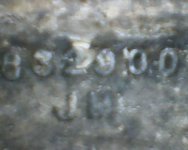
The prop shop was able to find the prop identifying numbers under several coats of paint, and did fortunately still have a new Michigan wheel 15x17 prop left in stock, Unfortunately the "wrong" hub length. So I will be rereading the posts concerning correct spacers/spacing.

The Allen screw provided with the new cone is too large to fit in the end of the shaft. Will using the old one be okay? Or is that a No-No?

What is the best, in your opinion, nonstick grease to use on the shaft to prevent corrosion and siezing as I just experienced.

One of the reasons I am so interested in re-habbing this boat, is that altho it is 37 years old, there is no deterioration in the fibreglass and gel-coat, nor have I yet been able to find where so much as a splinter of wood was used in construction, except the teak dashboard. All that, and I got it and the trailer very cheap. LOL

Thank you again, and I may be back once I start servicing the ltfi mechanism.

Jerry
 
Jerry, we really need to see photos.
You just now mentioned "the Allen screw provided with the new cone is too large to fit in the end of the shaft."
The only props shafts that are internally threaded for the Spinner center keeper bolt, would be the 280 and later, and the 275.
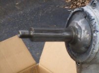
The 270 prop shafts were not internally threaded.

NOTE: in order to use the long hub propeller, the prop shaft must be internally threaded so that the AFT-Most portion of the 2 pc spinner and center locking bolt can be used. Otherwise, we have no means of locking the spinner when a long hub prop is used.

Jerry, any water proof grease, or in a pinch, any grease that does not contain conductive materials can be used on your prop shaft and inner splines.
Conductive materials (automotive Anti-Seize for example) will actually accelerate corrosion.
 
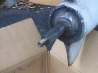
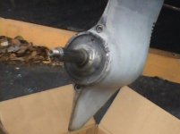
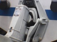
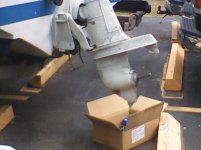
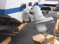
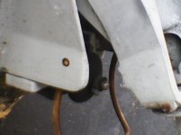
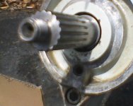
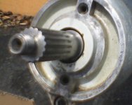
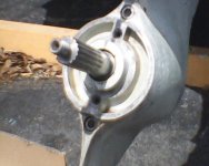
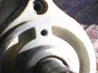
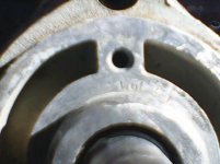
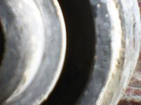
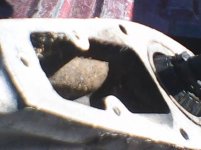
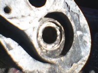
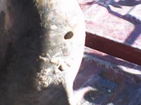
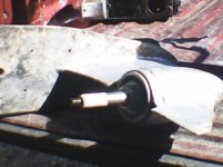
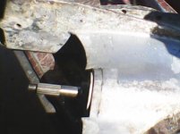
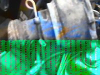
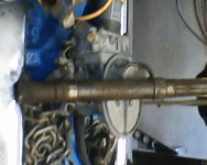
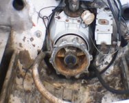
Below are some pictures of the drive. hopefully they are adequate.


BOAT 004.jpgBOAT 005.jpgBOAT 006.jpgBOAT 007.jpgBOAT 008.jpgBOAT 009.jpg

The new prop seems to fit well using only the prop, locking ring and cone. The small hole in the back center of the shaft is unthreaded. Rain showers today cut my time short and tomorrow I will do more extensive measuring.

I also put on a new Zinc. Stamped into the housing underneath, were the letters A B S in the outer ring of the housing. Next to the shaft, on the inner ring, there was the number 215. Does this portend a gear ration problem for me?

Thank you

Jerry
 
Jerry, here's what I think you have:

You've got a 280T transom shield with an early intermediate housing, with who knows which transmission, and with a 250 or 270 lower unit that is NOT threaded for the spinner center locking bolt.
The lower unit has the exhaust outlet blocked off and a large trim fin/torque tab in its place.

This prop shaft requires the short prop shaft spacer/line cutter only..... Repeat... the short spacer/line cutter ONLY.

Because the prop shaft is NOT internally threaded, you cannot use the long hub propeller. There is NO means of locking the aft-most portion of a 2 pc spinner from coming loose, as I mentioned earlier.
Two things are against you:
1..... The SS lock tab will have ZERO splines to index onto.
2..... Even if it did latch onto the shaft splines, the aft-most section of the 2 pc spinner does not offer the castellated areas for SS tab washer "tabs" to be folded into.
The only locking means would be to drill this and use SS safety wire.

As you can see, it looks as though someone has put a zip tie on the tip of rubber boot at the AFT-most end of the hydraulic cylinder.
This rubber boot part will be nearly impossible to find. I'd be very surprised if you could find a good used one.

I'd nip this in the bud right now, and I'd pull that transom shield and I'd pick up a 280 4 cylinder transom shield and install it.
The 4 cylinder shields are a dime/dozen.

I'd also remove the ring anode and wire brush the rear of the prop shaft bearing carrier and expose the ratio numbers.
The V-8 ratio will be 1.61:1 and will be stamped into this carrier.
 
Thank you for the assessments. The present situation is this. The new prop does go on far enough with the present line cutter to allow the lock/tab washer to fit nicely into the splines on the shaft. I am assuming the cone nut it locks is what you are calling a spinner. I is one piece and firmly butts up against the lock washer, allowing it to be locked.

The bottom rubber seal on the tilt motor is not a problem I have looked into as yet. But, it does remind me of a style and configuration used on hydraulic master cylinders from 1950's cars and trucks.

Consequently I will need to find a way to jury rig my way around my problem till I can find the needed solution on Craigslist, ebay, a used boat salvage yard, or just buy a donor boat.

Today I will take some photos addressing the tilt cylinder/motor and post those later this evening.
 
1.... The new prop does go on far enough with the present line cutter to allow the lock/tab washer to fit nicely
into the splines on the shaft.

2.... I am assuming the cone nut it locks is what you are calling a spinner.


3.... I is one piece and firmly butts up against the lock washer, allowing it to be locked.

1.... OK.... this is NOT a long hub prop.
What you have is a full length blade hub prop that looks like a long hub prop.
The spline portion is actually in the short hub category. That's why you are able to see the SS tab washer index with the shaft splines.
If this was truly a "long hub" prop, the prop shaft splines would be into the spline hub approximately 1/4" or so. IOW, 1/4" shy of
protruding from the hub.
This is why the AFT-Most portion of the 2 pc spinner is required.... because it actually reaches into the propeller hub as to give enough thread contact.
But when these are used, the SS tab washer cannot be used.
Since the shaft is not internally threaded, we aren't able to use the locking bolt.
This leaves us with no means of locking the spinner.

You may want to bring your prop shop up to speed on this. (see below)

2.... Yes... that is a "spinner" and is available as a 1 pc or 2 pc. Many call it a "cone nut".


3.... See #1 above.


NOTE for the AQ series drives:

With the correct prop shaft spacer/line cutter, all prop shafts net the same length of splines.
There is no long/short prop shaft when the necessary and correct spacer/line cutter is installed.


250, 270 = short spacer/line cutter and NO internal threads for center locking bolt.
Short hub props ONLY.

275 = short spacer/line cutter and internal threads for center locking bolt.
Short and Long hub props.

280, 290, SP and later = long spacer/line cutter and internal threads for center locking bolt.
Short and Long hub props.
 
Last edited:
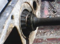
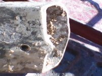
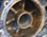
I went out, found and obtained, probably the worst example of a 280 drive with 1.61:1 gear ratio available. (pictures attached) I have spent a week getting it apart. Liquid wrench, heat and impact allen wrenches can be your friends! Smells like a oil polluted bay bottom at low tide. Thank the Good Lord, I only intend to use the lower part of the unit. It appears to have been completely submerged for an extended period of time.

The bearings of course will be replaced, hopefully the gears are at least salvageable. Any further cautions any of you may have will be greatly appreciated. It may be expected, but i have noticed a large amount of back and forth play between the vertical shaft and the prop shaft. I will be opening that tomorrow when a freind brings a puller by to pull the cap.

Jerry

BOATIV 001.jpgBOATIV 002.jpgBOATIV 003.jpgBOATIV 004.jpgBOATIV 005.jpgBOATIV 006.jpg
 
Jerry, the vertical shaft tapered roller bearing is rusted beyond use. You'll definitely want to replace this bearing and race.
Note that when this has been replaced, you'll need to go through the A and B dimension procedure and re-shim above this new race.
See the OEM specs and procedure for calculating the A and B dimension.

Since this bearing shows rust, I'm betting that the other bearings need to be replaced as well.
This will require some fairly decent Hypoid gear experience.

FYI and FWIW..... this lower is the 280 style and will require the long spacer/line cutter.
If the prop shaft is internally threaded, you are open to either the long of short hub props.

.
 
Just as an update. The rebuilding of the lower part of the 280 drive continues. Awaiting parts(read money).

Meanwhile at the boat shop, the rebuilt 351w is ready to be put back into the boat. Replacing the drive bellows and "S" tube of course was contemplated. BUT!, having heard so much from everyone re the Primary drive shaft bearings and since the engine is out, I put that on the schedule also. Good thing!

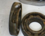
Found out existing bearings were frozen solid lumps of rust. It is readily apparent that had the engine been installed with those still in, it would not have been able to turn over to even start. I surmise that the engine, damper plate, and drive shaft are a unit until the transmission on the drive.

Being new to this, Thank you Gentlemen for your continuing advice.

The amount of time this is taking annoys me only from the standpoint, that the time in the boat shop precludes my working on other neccessary jobs.

"It's hard to remember the original job was draining the swamp, when you are up to your ass in alligators".
 
I should have added.... if this is a single bearing, and if there is a grease port in the flywheel cover for this, the bearing must be an "Open" bearing, and the grease cavity must be pre-filled.
If the flywheel cover does not have the grease port, the bearing must be a "sealed" bearing.

.
 
Called the Boat works and they confirmed what I thought I saw. Two bearings, both rusted lumps. Neither looked like a sealed type bearing. They had been pulled off by the time I saw them. Also neither looked as if they had ever had any sealing plates over the balls in the bearings.

The shaft itself from what I saw is in good shape. No pitting, wear or any other unseemly features that I could see.

LOL! what kind of trouble, mismatching does this portend?
 
Forgot to mention, the bell that houses the driveshaft has no grease fittings whatsoever.
Jerry, several things come to mind for me.

There are a few Ford F/C's that are 1 pc.
The Ford Fywheel Cover (for the Volvo Penta) is typically a single bearing PDS with a pilot nose at the FWD end.

These are sometimes a separate Ford Borg Warner F/C with a Glastron, Eaton, Holman Moody, or Donzi Volvo Penta PDS adapter housing attached to the F/C.
These are sometimes equipped with a lube fitting, which means that the bearing will be an open bearing.
These are also sometimes NOT equipped with a lube fitting, which means that the bearing will be a sealed bearing.

If this is for some reason equipped with two bearings, and no grease port, the two bearings better be sealed bearings.
If you were to loose this bearing at high speed and while up on plane, the damage will be costly.

I'm mentioning this to you so that you can verify what this shop is doing for you.
I see mistakes that have been made, and mistakes currently being made all of the time.

.
 
OK, that is not a Volvo Penta PDS housing for the Ford.
That is a Borg Warner/Volvo Penta PDS adapter housing.... and it is NOT Volvo Penta.
It takes the Ford B/W Flywheel Cover, and adapts it to this B/W PDS adapter housing.

Many of these were Donzi, Holman Moody, Glastron, etc.
These set the engine forward by 3-1/8" or so.
The steel PDS was made by one of these companies also.
Borg Warner splines at the FWD end.... Volvo Penta course splines at the AFT end.

There should be a grease port in this B/W.... V/P adapter housing.
If so, then these will be the open bearings.

If the OD of both bearings is the same, they will be a 6206 and a 6007.
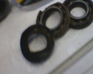
Seals will be 35x62x7mm in a TDM or Timken rubber encapsulated.

If no grease port, you will have to use sealed bearings.

.
 
Not sure if this is a return to the tree of knowledge, or the fount of information. LOL

The "restoration" of the drive system is coming along, if slowly. The engine is ready. the stern drive after extensive repairs to the lower 289 unit I purchased is almost ready. The repaired PDS and bearings have been reinstalled. A short piece of 4x4 totally encased in fibreglass used for the forward motoer mount anchors turns out to be the partial victim of rot. Since there are no walking wounded allowed, and the bilge needed new gel coat anyway, it will be totally repaired. I did a lot of poking and prying, and everything else remains solid, floors, stringers, and any etc's there may be.

However:

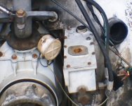
This being my first ever sterndrive, and because of it's age, there are things that even the 1/3rd my age mechanics can not tell me about this 37 year old boat. I am attaching photos of a metal box (resevoir) which has hydraulic type hoses going to the lift, unit.
I think there is supposed to be a motor on top of it. I have no idea what it looks like or where it may be obtained. the box looks as if a contains a pumping mechanism.

Since it is a seperate unit, (just being hung out of the way in it's presnt location) could there be an aftermarket type hydraulic pump system, or even one from some other sterndrive maker that could be used.
Thank you,
jerryLASTLEGS 001.jpgLASTLEGS 026.jpg

Please! no comments regarding the bilge, it's being worked on before the engine goes in.
 
Look on e-Bay.
New pumps from Bob-Tail engines are separated and sold often.
This must be a Power Trim pump..... not a trim tab pump.

As for the hose connections....., you're on your own. Most likely you'll have these custom made.

As you know, you are attempting to resurrect a drive system from the grave that should have remained there.
I love the Volvo Pentas..... but this T drive was a problematic drive.
 
Back
Top