After taking a closer look at the inner transom assembly (link is for 1987 but is good for visual)
http://www.marineengine.com/parts/m...-1987/0b525982-thru-0b773304/flywheel-housing
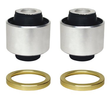
The rubber bushing/mount referred to looks to only have lateral (side to side/rotational) movement. No vertical movement as the center of the bushing has a steel sleeve. Does this steel sleeve go all the way thru the bushing or is it two pieces and when the bolts are tightened it compresses it?
I have never gone that far into a inner transom assembly and removed or had to replace these "bushings".
If the sleeve is one piece it looks to me that unless the double helical lock washer that goes between the bell housing mount and the inner transom mount is broken or missing there should be no issue .
If the rubber wears out the engine would have side to side slop and not up/down slop unless the inner steel sleeve has been crushed/damaged etc..
Maybe someone could explain this "sagging" that has been mentioned. what "sags" other than my stomach!!