Logo

AQ171C Alternator Question?

moresparks

Regular Contributor
Please can someone assist?
I am trying to get to the bottom of the wiring on my alternator as I want to upgrade the system.
The current layout is ether wrongly wired or very crude.
Basically I have 2 Batteries. Engine Start and House Battery. Currently the alternator has a D+ feed permanently wired from the un- switched house battery isolating switch.
It currently works, however I am not happy with 12v permanently wired to D+ as this causes a battery drain as well as not being able to isolate the battery quickly.
My guess is that the current D+ 12volt feed is from the house battery to supply the “excitation”. The thickness of the cable (6.0mm2) is probably to charge the house battery and was a factory install. The probable reason it was from the un-switched side was to prevent “user error” as if the house battery switch was accidently not switched on, then neither of the batteries would be charged.
Completely disconnecting the D+ wire and the alternator does not charge even when revved hard.
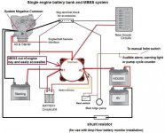
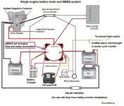
The alternator is a Prestolite 66021151MS and according to the circuit diagram of this model, then a D+ is required to “excite” the alternator. Normally this would be a 12v feed from the ignition switch with a warning lamp.

The resistor (22) in the diagram is missing.
Does anybody know the location of the Solenoid Valve (25) or what it looks like? This is so I may be able to trace the circuit from the wiring loom.
I will have a think over the winter and maybe come up with a better solution like running a separate 12v cable from the ignition switch via a fuse and lamp or the 834784 Volvo resistor. Then fit an Automatic ChargeRelay to charge both batteries.
 

Attachments

  • Scan0001 (2).jpg
    Scan0001 (2).jpg
    49.9 KB · Views: 221
You should have no issues if your MBSS is cabled correctly.
(MBSS= Main Battery Selector Switch)

Your alternator charge lead will make a connection to the MBSS common cable via the starter motor's solenoid terminal.
From there, YOU direct the charge rate via the MBSS selection.
Likewise, YOU select which batt bank you will be pulling current from via the MBSS selection.

Crank your engine on #1, your SLBB (start load batt bank).
Warm engine while the alternator replaces the AH used for cranking (it does not require much).

Once warmed up, you can switch over to #2, your HLBB (house load batt bank).
You will be adding to the charge rate of this bank of "Deep Cycle" batteries while you cruise.


This is one very basic and very simple manual battery management system that works well for many.
An ACR or VSR can be added if you feel it necessary.
 

Attachments

  • MBSS and Negs for Mike Casey.jpg
    MBSS and Negs for Mike Casey.jpg
    69.3 KB · Views: 208
Last edited:
Many thanks for your responses.
I have been tracing wires with a multi-meter and found abrown wire that has been cut –off. This traces back via pin 7 of the wiringloom connector and eventually to the instrument light switch (8). There is alsoa purple feed to the Electronic Ignition Unit via pin 7 also. The resistor unit is completely missing.
When the ignition switch is turned on then 12volts appearsat the cut-off brown wire, actually its 0.5 volts lower than the main batterysupply – I assume due to cable and switch losses. I am pretty confident that really should go toD+ to the alternator via the resistor unit as in the original circuit diagram.
I believe (maybe mistaken) that the current wiring was acrude attempt to charge the second battery when the engine is running. I have temporarymoved the D+ fed wire to the other side of the switch.
I have ordered a resistor unit and will wire as in thediagram and for charging the second battery I will go the Blue Sea ACR route,mainly because it is easier without major rewiring.

 
When you leave your boat attended, your MBSS will be turned OFF.... Yes/No???

If so, this means that with exception to your main bilge pump float switch and perhaps pre-set AM/FM radio memory, all 12 vdc power will be cut.
Only the float switch and radio pre-set will be powered.
All instruments, lights, starter motor, ignition, alternator, etc. will not have 12 vdc power.
This is one purpose of the MBSS or BS.


As for the alternator..... some of the older Volvo Penta electrical systems had issues whereby the alternator field circuit was derived from the ignition system power. In other words, the ignition power also powered the alternator field circuit.
If the little in-line diode/resistor failed, the alternator could continue powering the ignition system, in which case the operator had no ability to shut the engine down.

With what we call the Delco 10si "1 wire alternator", this is a non-issue.

The Delco 10 si 1 wire unit will not self excite until around 1,200 rpm.... but once excited, they will remain excited at all engine speeds until engine shut down.
They are a good, reliable, and relatively inexpensive alternative.


Back to the battery switch (MBSS or BS) for a moment.....

Understand that a correctly set up system will include multiple battery banks.
#1 = SLBB, a dedicated cranking battery.... and #2 = HLBB, a bank of Deep Cycle batteries.

Your MBSS will let YOU select which bank you want to use for starting, lights, instruments, radio, etc...... and which bank the engine alternator will be sending it's charge rate to.
Of course it's best to crank on a Starting Battery, and of course it's best to operate your House Loads from Deep Cycle batteries.

An ACR or VSR will help with alternator charging in that each bank (regardles of MBSS selection) will receive this charge rate.


.
 
Last edited:
Just to answer a couple of questions I have 2 key type Battery Isolating switches, one for each battery.
“When you leave your boat unattended, yourMBSS will be turned OFF”.... Yes/No??? - Yes
“All instruments, lights, starter motor,ignition, alternator, etc. will not have 12 v dc power.” – It doesn't now! Previously there was a Permanent 12volt feed from the house battery to D+ (Field Circuit).
I have the Prestolite Alternator and this does need the D+ wired from a 12volt source to charge, I have tried without.
“As for the alternator..... some of the older Volvo Penta electrical systems had issues whereby the alternator field circuit was derived from the ignition system power. In other words, the ignition power also powered the alternator field circuit.” I assumed that would have been preferable but stand corrected.
“If the little in-line diode/resistor failed, the alternator could continue powering the ignition system, in which case the operator had no ability to shut the engine down.”
I have heard of these issues! There is a handy 12 volt feed fairly close by the alternator fed from the Cranking Battery, this is about 10 AWG red wire and has also been cut off. Would this be a preferable to the Brown wire? I was trying to wire the alternator identical to the diagram in my first post. I have no fuses apart from the instrument panel fuses. The main instrument panel and circuit breakers are in the main cabin and the wiring follows a torturous route through the bilges. As the brown wire was cut off near the alternator it seemed an ideal point to pick-up as this only has 12 volts when the ignition switch is on. Just need to trace the half volt loss!

With regards to the half a volt loss – I agree and previously have tried to trace without success – so far. I even made up a complete new wiring loom to replace and check.
The 2 batteries are different types the Engine Start battery is an engine cranking battery and the house battery is a deep cycle battery and they are new this year.
I am trying to remedy years of neglect and slowly working through issues and thanks to this forum have been having success. As the electrics were working I have left that until now.
 
For what it's worth, I have years of Marine 12 vdc experience that includes correcting bad wiring to complete re-wiring and re-cabling of Marine 12 vdc systems.
I find that most smaller boats can function very well with a system similar to what's shown in the post #3 schematic.
I also find that in most cases, the KIS (keep it simple) method works best.
Please take a minute, and go back to post # 3 and look again at the schematic that I posted.


The wiring schematic shown in post #8 clearly shows the instrument wiring and where it would make it's connection to the hull harness and eventually to the engine harness.
However, it shows a Master Switch, which generally opens and closes the circuit for a single battery bank.
You apparently have two battery banks.
With two battery banks, an MBSS will serve your needs much better, and will make battery selection more understandable.


If this was my issue and/or my boat, would focus on getting the engine data, instrumentation, lights, bilge pumps, blower motor, etc, circuits all back to the OEM arrangement.

I would get rid of the two BSs (battery switches) and I would install a good single MBSS........ Bluesea, Cole Hersee, Guest, etc. (steer clear of the 90* sweep Perko MBSS).

I would rid myself of any other alternator charge connections, so that the charge rate has no choice but to use the "common" cable connection at the starter motor solenoid terminal.


I would take my SLBB + cable to the #1 MBSS terminal.
I would take my HLBB + cable to the #2 MBSS terminal.

I would run one Negative cable from each battery bank to the engine block.
(this will be your "system Negative common" connection.)

The MBSS "common" cable will connect directly to the starter motor solenoid terminal.
Your engine harness will pick up it's 12 vdc from this point.

Your hull harness will also receive it's 12 vdc from the interface between it and the engine harness (usually a large multi-pin connector).
Your instrument panel will receive it's 12 vdc from the hull harness.

Now when either battery bank has been selected (MBSS set to #1 or #2), power will travel via the "common" cable to the starter motor.
The engine harness will now be powered.
The hull harness will also now be powered.
The instrument panel will also now be powered.

(when the MBSS is turned OFF, all power to these areas will be cut.)

The engine alternator charge will use this same path to send the charge rate to the batt bank that has been selected.


Here's the same schematic showing an optional ACR/VSR connection between battery banks.

(note that nothing other than battery cables make a direct battery connection)
 

Attachments

  • MBSS and Negs w ACR.jpg
    MBSS and Negs w ACR.jpg
    73.1 KB · Views: 118
Many thanks for that information it was appreciated.
I guess I had the rewiring idea in the back of my mind but was hoping to avoid it. What you say makes absolute sense but I was just avoiding the truth – ha ha!!
I am not too bad with 12volt stuff, no expert but can get by, so your proposals hold no fears – except in the pocket.
The boat will be coming out for the winter in the next few days so I will look through over the coming months.
The half a volt loss maybe tricky to find and I am not yet sure if this is normal as I have the full voltage at the ignition Switch “B”but lose just under half a volt at “I”? ”I” feeds the instrument panel meters and there is a take off for the trim tab meter etc. Disconnecting some of the cables made no difference but I have more to go. The worry is I have a half a volt less at the Starter Relay - 21 in the diagram.
BTW, the temperature sender wire is a different brown – its light brown and is connected all o/k, this also has half a volt less than the main supply.
Once again - all the help is much appreciated.
Thank you.
 
Mr. Moresparks, from what I read I don't believe that your electrical system is quite right... at least not as I would see it.
I sure hope that I'm not trying to take you in the wrong direction.

That said....... I took the liberty of using Kim's schematic and made a few changes to it showing the connection to the Engine harnes/Hull harness.

Your instruments and color codes may not be the same, but the idea will be very similar.

Also, I think that a small voltage drop in certain areas can be expected.
Perhaps I'm not fully understanding your concerns.
 

Attachments

  • schematic for Moresparks ME dot com.jpg
    schematic for Moresparks ME dot com.jpg
    62.2 KB · Views: 105
Last edited:
Back
Top