Logo

AQ series lift wiring

joe_merchant

Regular Contributor
I have the AQ280 out drive. Over time, it started sporadically not working, i.e., sometimes it worked, and other times it didn't. Finally quit working, although both relays did click at that time. Pulled the mechanism, cleaned everything up, changed the bearings, and tested it again. On the bench, the motor works fine in both directions by jumping the leads with a battery. Bench tested both relays, and they tested good. Put it back in the boat, and it only clicks in the up direction. Just to be sure, bought new relays, installed them, and now nothing. That is with the black box removed from the lift mechanism so being on too tight wouldn't be an issue.

Am assuming that I need to start with power from the helm, and see what is getting back to the wiring harness. I have the below wiring diagram. It gives me the basics so that I can get started, but mine is the two wire, not the four wire shown.
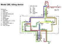
Lift motor wiring.jpg

I can get back to the connector, but want to test further. Anyone have a wiring diagram for the 2 wire system? Am assuming that I need to check the limit switch. It clicks and moves freely, just haven't tested it electrically yet. Also noticed that it lists item #13 as a fuse but I don't physically see it in my arrangement. Anyone know where I should be looking for this, and if most actually have a fuse?

And, of course, the new relays are too tall to allow the cover to go on, but I'll deal with that later.

Thanks in advance for the help.
 
Last edited:
Joe, this is not simple to explain.

First... if the electric motor has been operated outside of the relay system (i.e., operated by jumping the motor leads), and if it's been operated in the Retract direction, the cast iron clutch component will typically break.
This means that the vice rod is in the full UP position, and is depressing the micro switch button.
When the micro switch is depressed, the motor's Negative is taken away from it, and no further retract operation is possible.
This is by design to prevent the cast iron clutch component from being damaged as it reaches the end of vice rod thread travel.

However, the extended vice rod direction is operational, but the vice rod will not extend due to the clutch threads being broken.
You will hear the motor operate, but there will be no vice rod movement.

Each and every one of these that I have repaired over the years (due to the clutch being broken), has been a result of the owner operating the motor without the relay and micro-switch system connected.

The other issues will be with the five pin relays if they have taken on water.


.
 
Last edited:
Rick, there is nothing wrong with the vice rod and clutch. I tested the motor to make sure it was working and to make sure that it would operate the vice rod. It has enough power to lift the outdrive, and the motor operates both directions. It was never over extended. To be honest, I don't know of any other way to reliably test the motor except by applying power to it.

As far as the relays being bad, there is no evidence of water in the box and the problem seemed to happen over a period of several trips to the lake. There were some times that it worked, and other times that it didn't. Now that the motor is and mechanical components are confirmed to be operational, my next step is to check out the electrical components. As I mentioned above, the new relays don't cure the problem. That is why I was asking about a wiring diagram for the two motor lead system.
 
Joe... me in blue text......

Rick, there is nothing wrong with the vice rod and clutch. I tested the motor to make sure it was working and to make sure that it would operate the vice rod. It has enough power to lift the outdrive, and the motor operates both directions. It was never over extended.
Over extending is not the issue.
I could operate any of these motors and extend the vice rod until it reaches the stop. I could then continue operating the motor while the clutch simply slips.
That is normal, and is what allows the drive to be pushed DOWN as the vice rod retracts without damage to the clutch unit.

When the vice rod is fully retracted by the clutch unit, that is when the cast iron portion can break... but normally only when the motor is operated without the microswitch in the loop.


Here's another way to explain what occures: (forgive any redundancy)

When the threads of the cast iron clutch portion lifts the vice rod (retracts), the cast iron portion of the clutch fully tightens down against it's brass counter component due to these threads lifting upwards on the vice rod.
IOW, the friction between the brass portion and the cast iron portion, allows the threads to cause compression between the two.

Conversely, when the drive's suspension fork arm itself lifts the vice rod (retracts), the cast iron portion of the clutch unit is being separated from it's brass counter component and releases or slips... as designed.
IOW, if the drive's suspension fork arm lifts the vice rod, it creates the lack of friction between the brass portion and the cast iron portion, and then causes the two to separate from one another.

Like said... it's difficult to explain without doing an actual demonstration.


To be honest, I don't know of any other way to reliably test the motor except by applying power to it.
Yes... if the relays are not working, there is no safe way to test the motor.... unless you were to stay way from the retracted position.


As far as the relays being bad, there is no evidence of water in the box and the problem seemed to happen over a period of several trips to the lake. There were some times that it worked, and other times that it didn't.
Have you looked at the lift-out unit helm switch-to-lift-out-unit harness?
There is a connector within this harness... probably somewhere near the transom area. This connector will look like a miniature version of your engine/hull harness connector... black boot and all.
Find this connector... pull it apart... spray a cleaner into the contacts..... reconnect... pull it apart again...... repeat several times.

Now that the motor is and mechanical components are confirmed to be operational, my next step is to check out the electrical components. As I mentioned above, the new relays don't cure the problem. That is why I was asking about a wiring diagram for the two motor lead system.
There are three schematics... one for the 4 wire motor... one for the 3 wire motor... and one for the most current 2 wire motor.
Do a Google search... they should come up.
 
Last edited:
Joe, I just found the 2 wire motor electrical schematic.
It can be found on page 164 of the OEM work shop manual titled "Aquamatic 280 280 DP 285 290 290 DP"
It won't let me copy... and I don't recall where I downloaded it from.... so you'll need to find this manual on line.
 
Thanks Rick. I changed the drawing a bit to make it easier to read.
View attachment wiring_diagram_2_wire.pdf

I'll start with making sure that I have proper signal from the switch to the end of the wiring harness (the plug you mentioned). I'll certainly try the trick of using contact cleaner, but right now, all three pins have nice shiny marks where they were making contact. Will clean them again anyway.
 
Last edited:
I think I understand. The last time that the unit was used electrically, the motor had the power to move the outdrive up. It was only up about a third of the way. I pushed down on the outdrive to verify the correct clutch friction, and it seemed acceptable to me. That was from jumping the motor leads. Since then, I've pushed up on the vice rod to get it out of the way of the outdrive arm so that it could latch.

From what I understand from your post, that should not have resulted in pressures on the clutch assembly that could cause damage since I did not use the motor to retract the vice rod (lower the outdrive).


Really appreciate the explanation.
 
..........

I think I understand. The last time that the unit was used electrically, the motor had the power to move the outdrive up.
It was only up about a third of the way.
Joe, and bent vice rod may be causing that.

I pushed down on the outdrive to verify the correct clutch friction, and it seemed acceptable to me. That was from jumping the motor leads. Since then, I've pushed up on the vice rod to get it out of the way of the outdrive arm so that it could latch.
Raise the drive up a bit, and place a piece of soft wood between the suspension fork arm and the vice rod presssure plate, then push the drive fully down.
This will raise the vice rod to it's fullest retract position.

If you have the amber helm switch light, the light will also go out.

From what I understand from your post, that should not have resulted in pressures on the clutch assembly that could cause damage since I did not use the motor to retract the vice rod (lower the outdrive).
When the vice rod is lifted by the fork arm, the two clutch components separate and the clutch slips.
However, when the electric motor does the retracting (via the double Acme threads lifting action), the cast iron portion presses further into the brass portion, and the clutch does not want to slip.

What spares the cast iron double Acme threads, is the micro switch as it takes the electric motor's Negative out of the loop.

Really appreciate the explanation.
Hey... it's good practice for me! :D
 
Last edited:
Back
Top