Logo

Alternator and or charging system question

1973 Browning Marine

Regular Contributor
I have a 65 amp marine 3 wire alternator setup. I also have two batteries installed beneath hatch of forward deck. I also hooked up (two) 8 fuse panels, one for each battery.
I also installed two grounding blocks for each battery. Also ran heavy duty battery cables to the one battery and to starter lug and a heavy ground on block itself. The one battery is going to be dedicated to the motor, bilge pumps, blowers,running lights,and guages. I was hoping to dedicate the other battery to electronics such as fishfinder (sonar), gps system, vhf radio, stereo. OK, now that I have gotten that off my chest, this is what I think I am trying to accomplish:
1) Keep the engine system battery isolated or seperate from secondary battery system
2) Use the second battery for electronics

Question is this: Can I take the exciter wire on alternator and splice into it in order to charge second battery. I have the first battery wired and it does charge properly. Also, is there any problem with using the 65 amp alternator to maintain charge on both battery systems? And what would be the easiest way to go about it? thanks, Tom
 
Lost ya Doc on the isolator? Are you referring to a Perko switch of some sort? Basically, I guess what I am trying to do is keep one battery separated from the other so if my alternator were to take a dump while I was out on the water, I would have some chance of making it back to shore on the other.
P.S. Taking kids to get ice cream so I probably won't respond for about an hour thanks, Tom
 
I think that your proposed approach is lacking some information, and possibly some understanding. No offense, please.
1973 Browning Marine said:
1) Keep the engine system battery isolated or seperate from secondary battery system
2) Use the second battery for electronics
Your two concerns can be easily addressed without separating out your your hull's OEM wiring and charging system! There is NO need to do this, IMO. In fact, it will very likely further complicate things for you. Keep it simple!

You are going to have two battery banks, correct?
A dedicated starting Battery ..... aka "Cranking Bank", and a dedicated "House Bank", (aka "House Load Bank") for cabin lights, radio, heater fan, electronics, etc.
The House Bank will be ideally made up from one or more Deep Cycle batteries.... NOT a Cranking Battery.
The two are entirely different in construction and intended usage. Cranking for starting.... Deep Cycles for house bank.

You need a method for both isolating and selecting these battery banks.
I would use an MBSS.... ( Main Battery Selector Switch) ... key word being "Selector".
(aka OFF/1/BOTH/2 switch like this one)
images

Here are the rear connecting terminals #1, #2 and "common".
images


The cranking battery is usually cabled to the #1 terminal, and the House Load Bank is cabled to the #2 terminal. Either bank remains isolated until either #1 or # 2 is selected.
Power then feeds through the "common" cable to the engine's starter motor. This is the point at which the Engine Harness and the Hull Harness interface with one another, and eventually power the helm.
The "common" cable doesn't know the difference, other than the available Amp Hours that can be supplied between the two entirely different battery types (heavy cranking amps -vs- the Amp Hours available from Deep Cycle batteries)!
Either can be selected, while the other is held in "Reserve"..... key word = "Reserve".
This should cover your concern about the alternator taking a dump on you.

These two banks can become "combined" when the "BOTH" selection is made....... but this should be a rare occurance, and should NOT be done routinely, IMO.

Agian.... no matter which bank is selected, the engine harness/hull harness will not know the difference.
Likewise with alternator charging.... the alternator will charge which ever bank has been "Selected".
These are "Make-before-Break" switches, so changing selection with engine running, is not an issues.
However, Do NOT switch to OFF with engine running!


Here is a basic schematic that is very simple, yet works tremendously well in most single engine boats.
I'm showing "new house loads", but pay no attention at this time. Just think in terms of your OEM hull harness and engine harness interface amd helm power.
I'm also showing 6 Volt House Bank Batteries paired up in series..... this is common for larger cruisers.... (more available Amp Hours w/ 6 volt batteries in series).
Yours can just as easily be 12 volt. Your call on that!


Note where the on board charger leads make their connection.
There is no need for any direct battery connections, other than battery cables ONLY. That's what the rear terminals are for.
An O/B Charger will still charge, regardless of MBSS position or selection, including OFF.
This also prevents the "rat's nest" at our batteries, and avoids small terminal corrosion.
Again, your call on that!

Ideally, we want to crank and warm engine on #1, and switch to #2 bank, keeping #1 in reserve for the day.
The bank that is currently selected, is being drawn from, and charged to via the engine alternator..... this includes House Loads!
NOTE: For a standard single engine system, people often confuse the separation of starting battery and house battery.
The ONLY separation takes place via the selection of the MBSS. Nothing else changes. A cranking bank will supply 12 vdc house load power...... likewise, a house bank will supply 12 vdc cranking power to the engine. It's just that these are the wrong battery types to be using inadvertently, and/or for any length of time. The two types have specific purposes.
So as you can see, an MBSS and two entirely different battery banks, requries that we manual manage these by selecting the intended battery bank. No big deal for most of us! We just get used to switching accordingly.


An ACR or a VSR can be added to take care of charging both banks automatically, regardless of MBSS selection.
There are also some great Bluesea products that further combine and isolate............ but that may be for another topic.

KIS.... Keep It Simple, and your system will be much easier to maintain and understand.
 
Last edited:
I think you're on the right track in wanting to keep the two battery banks completely separate. You shouldn't wire the alternator the way you were thinking though. This will tie both batteries together and make them one bank. The above replies are all pretty common methods of isolating battery banks using selector switches, ACRs, isolators etc. Though it's great to isolate, it's also desirable to be able to join the banks together temporarily should your start battery fail to start the engine for example.

Though I'm in favour of using "ON - OFF" battery switches to be able to shut off power in a given circuit, I am not in favour of using the selector switch with the "1 - 2 - BOTH" function. As mentioned above, it simply requires more attention than most people are willing to give when on the hook and partying for the weekend, only to find they can't start the engines becasue they forgot to switch back to "1" or "2". This is the number one reason for calls on the water by the way.... dead batteries. I personally don't see the need to switch from one battery to another. My suggestion is to keep the banks separate as you've started with, an "ON - OFF" switch for each bank, a means to charge each bank while keeping them isolated, and a method of joining the two banks for emergency starts.

There are several methods of accomplishing all this but I'll touch on the ACR. An ACR offers battery isollation, and when it detects a voltage high enough that it percieves as a charge current (engine running and alternator putting out an expected charge voltage), it joins the two banks together. When it does not detect a charge (engine off) it disconnects the two banks thus maintaining the isolation you have designed into the system. ACRs come with options as well; some have a built in manual paralleling function that can be activated from your dash, others combine the banks for start up automatically, and still others offer a means to adjust cut in and out voltage settings. Installation is easy in my opinion. A simple DIY version of an ACR can also be a continuous duty solenoid (get marine grade) controlled by the ignition switch that joins both banks when your ignition key is in the "Run" possition then disconnects when you turn the engine off, leaving the banks isolated. As long as your engine is running, you charge both banks, when you shut engine off, banks are isolated. Very simple, nothing to remember or think about when you're trying to have a good time. To add and emergency start function, throw in a temporary push button that you activate before starting the engine.

Battery isolators are good simple devices but diodes have an inherent voltage drop across them of about .7 volts. In a 3 diode unit (1 alt and 2 banks) you could have a minimum 1.4 volt drop (one bank). Unless you can adjust your alternators output, this is not a good thing.

That's my 2 cents. Hope it helps.
 
Last edited:
WoodieMan, without Tom posting a proposed schematic, I did not even attempt to understand what he is suggesting. So I was unable to elaborate on anything, other than a proposal.
He sorta lost my attention at the point of asking;
Question is this: Can I take the exciter wire on alternator and splice into it in order to charge second battery. I have the first battery wired and it does charge properly........... Tom

WoodieMan, I fully understand the use of an ignition triggered relay for combining... I've done similar for my own twin engine system, but via the use of a momentary helm switch..... I could easily make this automatic, but need it to work in an either direction scenario. I don't mind one bit that it requires me to manually operate a momentary switch. I have rarely had the need to use it.

I still beleive that an MBSS is a good solution for Tom, in that a single switching device is capable of joining two indepent banks (one at a time), with one common source to the engine. Nothing needs to be done to the hull harness and engine harness interface, and he need not worry about his engine alternator charging. He could certainly use an ACR for charging only.
Agreed......, there may be a little risk in managing an MBSS, but unless we are just too dang forgetful, it's extremely minimal.
If forgetful.... then yes, we need a fully automatic system, and an ACR may do the trick.
On that merit, I'd tend to agree with you.


I think in order to go any further here, Tom needs to post a proposed schematic.... or grab one from the Internet, and doctor it up.
Tom, where are ya? :)

Yes... ditto not using an isolator. Not with today's available ACR's. Isolators are very old school technology.
 
Last edited:
Rick, couldn't agree with you more on the isolators.....old school. Gonna stand firm on the selector switch though. If one is going through the trouble of rewiring as it seems to me Tom already is, then I say take the need to remember out of the equation. I'm with you Rick on some of us who are aware of the mechanics and consequences of being forgetful with power management, hense it is second nature for us to keep on top of the switch's position. However, I've learned over the years that there is a different type of boater hitting the water these days (I'm sure you'll agree!!), they just seem more callus or careless. It can't be for lack of education on such matters as the internet is a great source that wasn't around before. It just seems people don't think anything will happen to them or that there will always be someone else around to pull them out of a hole. Several manufacturers have stopped using the selector switches for reasons I've stated. I haven't installed one for years, and have experienced that no matter how much of my time I spend educating someone on it's propper use, they still get in trouble. I say don't install them, suggest a better option albeit perhaps a bit more wiring but the result will be one less thing to remember when kids, wives, girlfriends, beer, weather, anchoring, sea-dooers etc etc are around.

To throw another wrench into the works, I don't like charging two dissimilar batttery banks (crank and deep cycle) with the same charge line. In this case with one alternator however, I don't see a choice. In my case, one engine charges cranking banks and the other charges deep cycle bank with everything being isolated by solenoids when not being charged.
 
Last edited:
Ricardo, sorry about the laymans terminology. I was brought up around trucks and equipment and I am by no means anywhere as knowledgeable as you folks with respect to the marine environment. I did not post sooner because had a bunch of kids over last night and got sidetracked. (lol) Really appreciate all of your responses, and I believe you have given me the best possible solutions for my needs. I failed to mention last night that the "cranking battery" is hooked up and is of the right type. Also, the "house battery" currently isolated from cranking battery and is hooked up to its own fuse panel beneath dashboard but has nothing to supply charge at this point in time. I like the idea of the MBSS setup because of its simplicity and understand that as a boater I would have to be responsible to manually change battery selection as need be. I also liked the idea of the ACR that docksidemarineservices and WoodieMan mentioned and never thought of using a marine solenoid off of the key switch. (pretty slick!lol) But, I think the MBSS would be my easiest solution at this time and I guess I could drive you guys nuts at a later date if I were to go the nine yards with all the rest of what I call "goodies" haha. Definitely got some great insight on many possibilities! Thanks so much, Tom
 
Well, on the issue of On/Off switch -vs- an MBSS, we must simply agree to disagree. Agreed? LOL
If two On/Off switches are used, and if each are being sourced by an individual battery bank, then they must somehow both feed the starter motor solenoid. Correct?
I agree that one or the other would need to be switched ON, in order to power the engine/hull harness.
Could a mistake not be made here? I think so!

IOW, could an owner not inadvertently switch to the House Bank when intended to start his engine? Or visa-versa? Or inadvertently leave both switched to ON? (essentially combining?)

I'd be interested in seeing a schematic from you.

Neener neener, you're it! :D

...........................
To throw another wrench into the works, I don't like charging two dissimilar batttery banks (crank and deep cycle) with the same charge line. In this case with one alternator however, I don't see a choice. In my case, one engine charges cranking banks and the other charges deep cycle bank with everything being isolated by solenoids when not being charged.
On the second issue above, I'm unclear as to whether or not you infer that I suggest charging both #1 and/or #2 banks simultaneously (unlike battery banks). I DO NOT support that idea, any more than you do. At least not for any charge duration.

With an MBSS, and single engine boat (as I assume that Tom has)....., the bank that is selected at the time, will be the bank to supply current and receive engine alternator charge.
Similarily, when the MBSS is selected to OFF, any O/B Charger leads will make an independent connection to each individual battery bank. There are ZERO issues with this scenario, other than leaving the MBSS set to BOTH.... this would not good, as this would "combine" these two banks!

BTW, there are no issues when two engine alternators are used to charge the same battery bank. Each appropriately cuts back as required.
Not sure if you were suggesting anything regarding this or not.

*******************

But good topic. Battery management is always a good topic.
It's also nice to have a civilized cyber converstion on the subject.
I participate on a large boating forum, where this is often NOT the case!:mad:

.
 
Tom not trying to convince you either way, what ever works best for you is the way to go. Before you proceed though, look at a wiring diagram for installing an MBSS and one for an ACR. Since it sounds to me like your wiring is basically done, I think you'll find the ACR much easier to install, and uses less wire. To install a switch now would mean breaking into the current wiring etc. In your case if I understand your installation now, depending on the ACR you decide to go with, you leave your wiring as is and it could be as simple as a wire to ground, and one wire from each bank to the ACR.
 
Ricardo,...............
I failed to mention last night that the "cranking battery" is hooked up and is of the right type. Also, the "house battery" currently isolated from cranking battery and is hooked up to its own fuse panel beneath dashboard but has nothing to supply charge at this point in time. I like the idea of the MBSS setup because of its simplicity and understand that as a boater I would have to be responsible to manually change battery selection as need be. I also liked the idea of the ACR that docksidemarineservices and WoodieMan mentioned and never thought of using a marine solenoid off of the key switch. (pretty slick!lol) But, I think the MBSS would be my easiest solution at this time and I guess I could drive you guys nuts at a later date if I were to go the nine yards with all the rest of what I call "goodies" haha. Definitely got some great insight on many possibilities! Thanks so much, Tom
Tom, I did not see your post while I was sword fighting with WoodieMan. :D

Tom, you've done sorta what I suspected you've done, by taking what you are calling your "House Loads" out of the loop, so to speak. As mentioned, I see little need to do this.
For one thing, it removes any possible redundancy when considering that in a worst case scenario, you may need to use the #1 cranking bank to supply your VHF radio in an emergency, for example. When the MBSS is used, we always have the option of switching to the #1 bank for redundancy.

I do, however, think that it's always best to bring a new/fresh dedicated circuit FWD for our Navigational equipment. Still being powered via the "common" source, but NOT using the OEM hull harness. This would be sourced at/from the same basic source as is the engine/hull harness, but again, not using any of the OEM wiring.
If the Hull Harness were to go down..... the new circuit will NOT.
WoodieMan would likely agree.

For this, see my schematic again regarding what I'm calling "New House Circuits", of which should actually read "New Nav Equipment Circuits".
All of your OEM house circuits (cabin lights, frig, running lights, heater, wipers, etc.) will be provide via your OEM hull harness...... but you get the idea.
These are probably best if left supplied via the OEM hull harness.
It's primarily our Nav equipment that we want a fresh circuit for.

Tom, if there is anyway for you to doctor up a schematic, please do so.
It will cut to the chase, and make this a whole lot easier to discuss.

Keep in mind that I'm not completely foo-foo'ing Woodie's On/OFF switch idea ....... it's just a personal preference.
I'll work on removing Woodie's training wheels later! :D
 
Rick, agree to disagree as stated. Also, no inference implied on the charging of dissimilar banks. Not quite sure about the scenario you are putting forth with the ON-OFF switch. Purhaps you are envisioning it differently than I or I simply didn't explain propperly. The ON - OFF switches have nothing to do with whether the engine starts off one bank or the other. They are simply there to shut each circuit off for servicing etc. They do not parallel the two banks and allow you start the engine from either one. The engine can only start with the crank battery period, unless you ideally incorporate a temporary parralleling device such as a solenoid as stated....my opinion!! And totally agree with you in other posts about keeping aux wiring away from battery posts; messy, anoying, and problematic.
 
BTW, one final tid bit here.
Whether On/Off switches, or an MBSS is used, DO NOT mount this in your engine bay!
Relocate to an area where you have easy access that does not involve lifting the engine hatch!
A slight added length to appropriate sized battery cables, is not an issue.

Battery management is further complicated for those who have to raise a hatch to access their switch.
It is also more dangerous if we were to need to shut down all 12 volt power in an emergency.
I've not had to do this, but I do know that I don't want to be moving gear, in order to raise my large engine hatch.


As for negative connections..... ditto. All negs must be equally as sound as any positives.
And on that note, there is redundancy when each bank offers it's own Negative cable connection to the engine block.

OK, I'm though preaching for a while! :D

Edit:
Tom and Woodie, can either of you post schematics? I think it would be great to see these.
 
Last edited:
LOL, Ricardo, I will have to get a good eyeball on what I have done with this thing tomorrow. It is in my shop garage. And I agree with you about some sort of schematic. And WoodieMan, I know that you were just giving me different alternatives and I really appreciate your help. At this point men, I am playing pin the tale on the donkey! lol talk to you soon, Tom
 
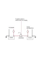
Here's the simplest form of what I'm talking about. My setup is much more complicated but I have a twin engine application and multiple banks to consider. The only issue with this set up as mentioned earlier is that the same charge line is charging two dissimilar banks, however in the grand scheme of things, and typical run times, I don't see it as a big concern. Haven't seen battery issues yet due to this set up. Best of all, it's pretty idiot proof.

Dual Battery.jpg
 
Last edited:
I am not sure about a solenoid bieng used that way, If left on (energized) for long periods of time it WILL fry!!! and it might take the boat with it.......I hope I am reading this correctly............
 
Kghost, continuous duty solenoids are used on bigger boats all the time. That's what they're manufactured for. Thier duty cycle is designed to for continuous operation. I wouldn't do it otherwise. Battery combiners use these as well. Not an issue, and works great IMO and others.
 
Last edited:
Kghost, I also use a continuous duty solenoid in a very similar scenario.
I use a momentary helm switch to excite a solenoid that momentarily combines Port/Stbd banks via my two MBSS "common" terminals.
Mine is not "ignition" switch excited, however, as is Woodie's.
I prefer to reserve the use until I deem it needed, since my Stbd side bank is adequate to crank from.
But it is there, and is ready for use should I need it.
 
Tell me if I miss understand......

Is continuos duty one that is cycles on and off continous? or stays on continous with no dentramental effects on the coil (solenoid)

If the answer is yes then my apprehension is continously ON for long periods of time which would eventually burn out the coil in the solenoid????

Maybe I am confusing continous against heavy duty where heavy duty would allow many more cycles of ON/OFF than a standard type such as the ones used for trim up/down......
Imagine that your wife gives you a looooooooong "Honey Do" list. Ya know, the type where the list never ends, and you can never satify her. Ya, that list!
That's "Continuous Duty"! :D
wives-nagging-wife-chain-ball-marriage-demotivational-poster-1285789937.jpg


On a more serious note..... yes, you have it correct!

Continuous Duty is not necessarily Heavy Duty, nor is Heavy Duty necessarily Continuous Duty.
Continuous Duty would be intended for long or full duration use, be it whatever the use would be!
I believe that both could be had in one relay or solenoid as well.

.
 
Last edited:
Not the answer I was looking for...........No wife!!! ................Do what I want........When I want.........

So continous on or continous on/off?
 
Kghost, not that you asked, and I know that you don't need a lesson. That is not my intent here.
This is rather just an FYI.

A solenoid does not necessarily need to be a contactor. A solenoid can be a magnetic/mechanical device only as well. No contacts, but the work load, via the plunger, may be moving an arm, or ___!
If a solenoid makes electrical contact, then essentially it is a "relay" switch, using the solenoid plunger principle.
A normal small current relay uses magnetic force to close contacts via an arm, so to speak, and without the use of a plunger.


The solenoid switching contacts are not the questionable area of Continuous Duty. Continuous Duty contacts don't care whether they make 1 contact, and hold.........., or make 1 contact, and immediately break.
The primary winding of the "pull in" coil determines if one can undergo short duty cycles, or a single "closed" cycle whereby it "holds". The "pull in" coil is designed differently. How? .... I'm not sure.
But these are designed to take the heat or resistance from the continued electrical current.

With Heavy Duty, the "pull in" coil may be intended for short or intermittent use, but the contacts are intended to be cycled many times, and for possibly greater amp loads. (larger disc/heavier contact posts)
(I doubt that these would be recommended for continuous duty.)

Bottom line, the switch that is being discussed, is basically a solenoid switch or relay, that can be left operational for long durations, and without damage to itself.

.
 
Last edited:
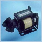
Kghost, great article, I'm going to keep that one. Ditto to what Rich said. All I can add is that I look at solenoids two different ways. There are those that act as switches which only have to overcome thier own internal spings that return the contacts to the normally open (or closed) position after power is disengaged, and those that are designed to pull an external hardware load (slide a piece of hardware).
Solenoid.jpgI was in the vending industry for a while and we used a lot of these, and yes as you stated before, man did they get hot, but they were pulling heavy hardware at times, not just overcoming a built in spring tention, hense the torque loads and heat specs in your article. In marine you may have seen them on electric fuel valves being used on top of fuel tanks now, and they stay on as long as engines are running.
Fluid Solenoid.jpg

On a side note, if one doesn't feel comfortable with using a continous duty unit, you can opt for a latching solenoid. On these, if I remember correctly, the coil is not powered up all the time, rather you feed the coil a pulse (temporary push button), it latches the switch and closes the load circuit then the coil powers down. When you want to open the load circuit, you bush the button again and the coil activates temporarily again and unlatches the contacts. This would work for Rich but not for me as I would have no way to pulse on and off through the ign. switch. Been thinking about it though, I'll probably come up with something eventually if I put my head to it again.
 
Last edited:
Woodie, not sure if I'd have a use for a latching solenoid, but I sure like the idea. You'd have unlimited switching locations. I think that there are some residential outdoor security lighting systems that work this way. Multiple Low Voltage switches throughout the home, with the solenoids in the main panel.

With all of this pull in/push out, latching this, latching that, open/closed, H/D -vs- C/D....... we're going to have Tom so dizzy and confused, that he won't be able to post here for a few days!
You still there, Tom?:D
 
Rick

I do have a good understanding on solenoids and what they do. What I was not aware of was they could be used like a relay.

Most of what I have used both in Marine and Machine Manufacturing, are the type that typically cycle on off wether with a mechanical link, open close a valve or to distribute power etc etc........Many years in industry. I just never had seen them used in this way. A relay yes a solenoid No.

I do understand all described above and also do not want to confuse anyone. The key here for me was the comparison to a relay. Even relays only like to be energized for so long........
 
Back
Top