Logo

2005 BF225 Starting and throttle issue

gentilebrian

Contributing Member
I just got a new boat with twin 2005 BF225's. Each motor has its own issue.

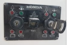
Port motor has the starting issue. First where the key goes the key has broken off in the ignition. When I was buying the boat it started right up and ran great. Then next time I went to start it the fuse for the ignition blew. Replaced fuse and tried again. Again the fuse blew. Then trimmed the motor a little and tried again and no issues. Now that I have it home when I try to start it I turn the ignition to on and the lights come on then I turn to start and nothing happens. With the ignition on I went to the starter and jumped it and it started right up. Any ideas?


Now the starboard motor. Runs great. Only issue is the throttle. When going from neutral to in gear at idle is fine. Going from idle to a faster RPM is very stiff at first but once it starts to move its smooth so when going from idle to a faster speed it jumps. The port motor doesn't have this problem and is very smooth from neutral to fast. This happens in forward and reverse and also with the neutral button pushed in and just moving throttle.

Any ideas?

Thanks in advance.
 
Tried a few things.
Port motor starting issue
First I swapped the wires on the back of the ignition key. Same issue when using starboards motor key and the starboard motor hooked to the port key worked fine.
Next I went back to the motor. Looks like the previous owner did a few wire repairs. Not sure what the wires do and the manual on Hondas website has a wiring diagram but you cant read which colors. The 2 colors are the RED wire and a light blue wire.

Haven't touched the starboard motor yet. Next step is to unhook the throttle at the motor and see how smooth it is. wire1.jpgwire2.jpg
 
Well good but bad news. On the port motor I pulled the leads from the neutral safety switch to test the switch and the switch tested fine. Hooked it back up and gave it a try and the motor started right up... If I had to guess its not the neutral switch that did it. I'm thinking its one of the other wires but now that it works I cant find out until it sneaks up on me.
 
There were a few wires that were "repaired". One was a red and the other was a lite blue. Any idea what these are for. Maybe its related? on the owners manual download you cant read what the wire colors are. I did just order a service manual but it will be a week or two before it arrives.
 
wiring issue,possibly where harness enters engine, resplice those suspect connections,or test them with a volmeter, the fact that a fuse blew twice there's a direct short to ground. Check for worn insulation,bare wire,loose connections on harnesses
 
Well now I am just confused. I am changing the wiring setup for the batteries to add a house battery. Currently each motor is setup with 2 wires from the motor to the battery. A 2 gage ground and 2 gage positive. The starboard motor starts just fine with this. The port motor however does nothing unless the assessory wire to the helm is on the battery.

Then I take a look at the back of the helm and there is a wire going from the accessory fuse panel to a white wire with a black strip on the port ignition spliced in. Whats this wire for. What are they trying to by pass.

I ordered the service manual but its not going to be delivered for a week or two so I dont know have a wiring diagram.
 
You obviously have issues at the 14 pin connector and possibly the wiring harness to from the engine to the helm.

A red lead to the helm is normally the overheat light lead....but it looks like the red lead is connected to a brown lead in the picture.A light blue lead goes to the down side of the trim switch.

As for the white/black lead going to the accessory fuse panel.....most likely there is a break in the white/black lead at the 14pin connector or in the harness to the helm. The white/black lead supplies power from the engine to the key switch and the trim switch. No power to that lead, you can not start or run the engine.

Pull the 14 pin connector apart and check for broken or corroded pins. They are replaceable.

Mike
 
Found part of my white wire problem. The wire was cut right where the wires go into the motor. Coming out of the 14pin there is 12v. I spliced in a length of wire and still not working so there must be another cut. Im going to have to order a new harness.

There are 2 harness part numbers. [FONT=&quot]32580-ZW2-D01 and [/FONT][FONT=Open Sans, Verdana, Geneva, sans-serif]32580-ZY3-000. Same description and same price. Whats the difference? [/FONT]
 
That seems to be a 14pin cable but does not have the extra leads for the pgm/battery warning lights. It is approximately 17 ft long. It will probably work, if it will reach and all you need is the 14 pins.

Here are the the Harness's that do the complete job. It has a 14 pin connector and a 6 pin connector at the engine end.

They vary by length needed.


[h=2]20 Wire Main Harness[/h]
32205-ZY6-015AH.jpg

[h=5]20 Wire Main Harness[/h][h=5]10 foot long
32205-ZY6-010AH
15 foot long
32205-ZY6-015AH
20 foot long
32205-ZY6-020AH
25 foot long
32205-ZY6-025AH
30 foot long
32205-ZY6-030AH
50 foot long
32205-ZY6-050AH [/h]

Mike
 
Thanks for the help. I will have to get one. I might just do all the cables while I am at it. All have some corrosion being a Salt boat but now that its being used in fresh time to clean it all up.
 
I ordered the 30' cable but the ends are different. On the motor side it fit as it should but the key side is very different. The new cable has white connectors and are a different type. The orange connectors are what is on my existing cable.

The Honda parts calls for 32580-zw2-D01. Any ideas?
 

Attachments

  • ert3.jpg
    ert3.jpg
    37 KB · Views: 44
  • 5432.jpg
    5432.jpg
    31 KB · Views: 40
  • 12342.jpg
    12342.jpg
    52.4 KB · Views: 34
If the orange connectors go to the key switch, they should plug into a key switch harness, which should have the correct connectors at the other end. Most likely, it is bunched up and wire tied under the dash. You just have to cut the wire ties and follow the harnesses. There should be a separate short harness going to each key switch.

They should look something like this....

36170-ZW7-110AH.jpg


Plug those connectors back into the key switch. Then plug the new cable into the other other end.

Mike
 
Your right. Thank you. I cut a bunch of wire ties and low and behold..

The New harness had 5 connectors at the helm side. One 6 pin one I didn't see where to hook it up. Also my trim from the throttle will only go up and not down but at the motor goes up and down from the motor switch. Maybe I didnt get a plug in all the way. Maybe Its the plug. Motor starts so Im good for the night. Dig into it tomorrow.
 

Attachments

  • mid.jpg
    mid.jpg
    50 KB · Views: 39
The extra plug/connector is for digital gauges...so you will not need it.

On the trim....you may have pushed a pin out. The lead to check in that connector would be blue. In the world of Honda green is up and blue is down. Just the opposite from American made motors where blue is up (like the sky) and green is down (like the grass).

The middle pin supplies the voltage and the switch connects it to the blue or green lead, depending on how it is pushed.

If it is not a pin problem, you can check to see if it is the switch or possibly something at the engine. If you use a paperclip or a wire to connect the center lead to the blue lead on the wiring harness and it does not go down, then you have an issue in the "blue" lead back at the engine.....possibly a broken or corroded pin on the 14 pin connector.

If the engine goes down, then there is an issue with the switch or a broken wire going to the switch. The break may be inside the insulation, where you can not see it.

It sounds like you are almost there.

Considering all that you have done so far, I am sure you will track it down.

Mike
 
Thank you. Yes the blue wire for sure isn't hooked up. The original cable they had cut and bypassed the big connector on the motor and I haven't hooked it back up yet.
 

Attachments

  • wire1.jpg
    wire1.jpg
    70.5 KB · Views: 41
Back
Top