Logo

2-STROKE OIL INJECTION - unexplained oil line

rmmu

Member
First time trying to bleed air from a 2-stroke oil injection pump on a Yamaha 40hp (3 cylinder).


The oil reservoir is inside the cowling. I'm puzzled by there being two oil lines between this reservoir and the oil injection pump.
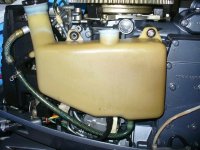
Photo of the reservoir attached below. Also a rough diagram to show the two oil lines.


In the diagram, line B is the main feed of oil from the bottom of the reservoir to the oil pump at F.
But there is also line A from the reservoir to the top of the oil pump with a check valve allowing flow only towards E.


Appreciate anyone able to explain why and when oil will flow through this second line?
 

Attachments

  • diagram4.jpg
    diagram4.jpg
    25.2 KB · Views: 3,908
  • yam40_oil_injectionB.jpg
    yam40_oil_injectionB.jpg
    75.5 KB · Views: 740
Since the check valve allows flow only in the direction of the pump (towards E), excess oil would then only arise at the time I fill (overfill) the reservoir; but why would Line A have two ports into the reservoir (up high and also at the bottom), and why flow excess oil to the pump - why burden it with the problem?

So I'm not sure how LineA can serve to handle excess oil.
 
Last edited:
To all readers of this thread - my apologies; I have now removed the Check Valve to clean it, and discovered it's direction is AWAY from the pump (not towards the pump as my first post stated). That changes things quite a bit.

Also makes Koditten's suggestion (post # 2 above) that it may be an "excess oil return line" from the pump very plausible.

So two questions come to mind:

1) Why are there TWO entry points into the oil reservoir from this return line when one would seemingly suffice?

2) Does this injection pump draw more oil than needed in order to provide cooling for the pump internals, like an inboard diesel engine does (which produces a strong stream of diesel return flow to the tank all the time)?
Is this the same cooling purpose and thus a steady return flow of oil would occur whenever the pump is operating?
 
The pump on your motor is an engine driven mechanical gear drive pump that connects directly to the crankshaft. The oil control part is controlled through The throttle linkage. The way it works is between the oil intake and oil exit is a cam. This cam is graduated so that it mostly covers the exit hole at an idle. As you throttle up more and more of the exit hole to the carbs is uncovered. At full throttle the pump exit is wide open. When you chop the throttle the reverse happens the pump exit gets covered. Since the engine will not throttle down as fast as you can chop the throttle. The pump being connected to the motor by a gear is pumping oil at a higher rate correlating with engine RPM. Since the throttle has been reduced so has the size of the exit hole because it is connected to the throttle linkage. This means for a couple seconds you have excess pressure until the motor gets to a stable rpm. You have 2 return points because if the oil level covers the lower one it can still go to the top one. Easiest way to bleed the pump is turn the bleed screw until oil comes out. Then disconnect the throttle linkage from the pump. Start the motor on a 50-1 pre-mix them manually turn the pump control to the wide open position and watch until the air is out of the 3 lines. Do this while the motor is idling then reconnect the linkage. The variable oil ratio is controlled by a combination of the port size and pump speed.
 
Last edited:
Thank you, Flyingscott, for taking time to write such a detailed description of the oil pump operation.

What you wrote answers very well the questions as to When and Why the pump would have to push out excess oil.

I appreciate it especially since 2-stroke engines over 25hp seem to be becoming very rare compared to 4-strokes, and thus there seems to be less expertise about outboard oil injection pumps around.

I only know as much as the typical weekend boater, but even so am actually impressed with the way Yamaha implemented the oil injection - the oil being injected AFTER the carburetors, thereby ensuring that only pure gasoline travels through the carb jets and (hopefully) those jets will stay cleaner without having to handle an oil mix.

Regarding your directions on how to bleed air from the pump - I really needed that tip as well. After I get to replace some of the hardened hose lines on the oil tank, I will unbolt the fuel pump (it obscures the oil pump somewhat) and try to get my first good view of the oil pump bleed screw. I'll be keen to report back here.
 
Get a manual for your motor preferably a Yamaha factory one. One thing I forgot to mention is that the pump is slightly overdriven. This means the pump does provide a little extra oil that needs to be bled off. That is because when you accelerate quickly it needs that extra oil until the pump catches up. Yamaha and Suzuki had the best oil injection systems of any carbed 2 stem outboards.
 
The oil pump Bleed instructions in the Yamaha service manual that I have access to - refer to the bottom part of this post.

Step2 in those instructions refer to removal of the air bleed screw. However, the accompanying photo in the manual is not close up enough for me to work out where exactly the BLEED SCREW is located.

So I attach a photo of the oil pump on the Yamaha engine I'm actually working on. The only "screw" I can see is a small philips screw head visible near the bottom of the pump body - small and hard to get to.

Question: is that really the bleed screw?

Bleed_screw_402.jpg


Bleeding instructions in service manual:

1. Prepare a 50:1 fuel mix, connect a flushing device and start the motor.
2. Place a suitable cloth under the air bleed screw. Remove the air bleed screw and allow oil to flow from the opening until a bubble-free flow of oil is obtained.
3. Install and tighten the bleed screw. Should the oil flow very slowly into the delivery hoses, check the vent on the oil tank to be sure it is dear.
4. Remove the cotter pin and then the link rod from the oil injection pump lever.
5. Turn the lever to the fully open position counterclockwise as far as possible. Allow the powerhead to idle at 800 rpm for about ten minutes.
6. Hold a suitable cloth under the oil delivery fitting at cylinder No. 1.
Remove the oil delivery line and allow the oil to flow into the cloth. Observe the oil flow for a few minutes to be sure no air bubbles are present.
Reconnect the line. Shut down the powerhead and remove the flushing device.
7. Connect the oil pump linkage and check its adjustment. With the throttle shut, the oil injection pump lever should be at the minimum stroke position.
 
Back
Top