Logo

1985 Gibson restoration/ Transom cutout

Brian Bell

New member
Thanks for having me, "first time caller love the the show".
Anyway hope to post a lot of pics as this goes on and have enough patients to finish, forget having enough money, the bank keeps sending boxes of checks in the mail to me so there must be money in the bank.
This started as a 1985 gibson standard with a 305/350 inboard coupled to a volve outdrive. All was removed and transom glassed back in. I am using a 350 bravo 2 transplant from a 1998 VIP, donner boat shouldnt matter but wanted to put it all in here, I like "bondos" attitude towards people on here that dont give up ALL or enough info.
Fast forward, im at the point were iI could make an expensive cut in my transom, the*info on page 10 in the instruction manual is not to clear, if anyone could look at that page and tell me how high up to measure angle I would be forever grateful. that angle is needed to use the chart on page 13 to determine the height of X.
AS of right now "mocking up" my Bravo 2 outdrive (its bolted to the gear case) and measuring from the cavitation plate to the top thru transom bolt its 22.5 inches. Now if i go in the engine box and transfer this demension, subtracting for bottom of glass thickness, line up my inner transom plate that is bolted to my bellhousing that is bolted to my bare mock up block with the motor mounts attatched and all this sitting on the stringer stands...........the engine is way to low in the front, saying not parrallel with the bilge bottom. As stated way earlier is this novel a 350 was taken out and am putting back a 350 so I dont believe adjusting the mounts up or modifing the stringers is the solution. Im thinking I have somewthing screwed up at the transom. Yes I do have the inner plate properly bolted to the bell houseing at first i had the aluminum spacer between the two.

Will take phone calls as well 757-576-7867 Brian

Thanks a million and a half in advance

Side note i still have the transom and engine box area from the VIP and i used it to make a template out of luan for the house boat.
 
I like "bondos" attitude towards people on here that dont give up ALL or enough info.

Ayuh,.... ;) Welcome Aboard,...

Yer goin' at this somewhat Backwards,... It's got Nothin' to do with where the motor sets, Now...

Do the measurements on the outside of the transom, to establish the Crank Shaft Centerline...
Drill, then mount the transom assembly...
Then hang the motor off yer alignment bar, to see where the motor mounts gotta go...
 
Understanding, but back to the question of at what verticle height would you determine transom angle to do the outside transom measurments?, cause on page 13 there is a 1 inch difference? (chart is not infront of me at this time) the the crank centerline could end up. Follow?
Guess I could use a swivle protractor but would have to adjust for the fact that the boat is not level front to back. That was me tayping/talking outloud.
Any input to that?
 
Guess I could use a swivle protractor but would have to adjust for the fact that the boat is not level front to back. That was me tayping/talking outloud.

Ayuh,.... Yer mounting the drive to the centerline of the Hull.....

A 4', or 6' straight edge, under, 'n along the keel's centerline is where yer gonna be measurin'...

Ditto the side to side tilt,... Square, 'n true to the Keel line....
 
I hope Bondo is still around and will also listen to anyone else as well.
Back in April when i started this phase of my build I had a heart attack and two mild stokes three weeks later, at the age of 41 and according to all the doc "your as fit as a horse", so things got put on hold for a while.
Enough of that, I managed to get the transom cut, inner and outter gimbal parts installed, temporarly install of the bravo 2 outdrive to be sure cavitation plate was flush with the bottom of the hull and its right on, bell housing and engine bolted together and the 350 with 350 engine mounts are 3 1/2 inches above the stringers. at this position/hight is the only way the aligment tool will freely slide in and out thru gimbal bearing into coupler. This also makes my exhaust manifold NOT parrallel with my stringers and the front of my intake manifold LOW this to me would allow my floats in the carb to be way off. Now i realize the boat will sit lower in the rear once its in the water but I cant see it being enough to level out the intake and manifolds. Am I over analizing this and need to simply build up my stringers? The boat was origonaly powered by a 350 BUT with a volve outdrive. Could Gibson have built different stringer hights for different outdrives?

Im at another stand still and asking for input. Thanks in advance to all
 
Brain, much of this is cut & paste from other postings that I've made over the years.
I know that you'll be using the Merc B drive, but the idea is the same with the A drive.
I hope that it fits your questions OK.


Brian, I believe that the X dimension for any certain drive, will be influenced by the V hull dead rise dimension and center line of crankshaft. If Merc wants a certain X dimension to be used for your hull, then that's where you would begin.

Make your transom cut out, mount the Gimbal housing and inner transom plate.
Install the engine and flywheel cover and fit this to the inner transom plate via the rear engine mounts.

Now do as Bill suggests by raising or lowering the front of the engine as to gain your correct engine drive coupler alignment.
(see image at bottom of page)
Be sure to load each side engine mount as equally as possible.

This will be new to you as the 1985 AQ series Volvo Penta drive does not require annual engine drive couple alignment.


Here's an example of a Merc A drive with a 7-1/4" X dimension used for a Sting Ray boat.
We'll see slightly different V angle and dead rise dimensions from boat to boat.

x_demesion.jpg


Here's another one with the Merc A drive with a 4" X dimension.

x_demesion1new.jpg


Note the narrow beam and V angle of this one whereby the X dimension is only 4".


You will not have any control over the Y dimension since many hulls incorporate a similar transom angle.


Here is another approach.
x_dimension_diagram_measure.png


You goal is to get the drive into the water stream, yet have your engine fit comfortably while offering adequate height adjustment for the drive coupler alignment.

Here's a simple explanation of engine drive coupler alignment.


Attachments

  • Drive Coupler alignment explained 4.jpg
    Drive Coupler alignment explained 4.jpg
    58.9 KB · Views: 11,008
  • Merc A drive X dimension.jpg
    Merc A drive X dimension.jpg
    24.2 KB · Views: 465
Last edited:
I hope Bondo is still around and will also listen to anyone else as well.
Back in April when i started this phase of my build I had a heart attack and two mild stokes three weeks later, at the age of 41 and according to all the doc "your as fit as a horse", so things got put on hold for a while.
Enough of that, I managed to get the transom cut, inner and outter gimbal parts installed, temporarly install of the bravo 2 outdrive to be sure cavitation plate was flush with the bottom of the hull and its right on, bell housing and engine bolted together and the 350 with 350 engine mounts are 3 1/2 inches above the stringers. at this position/hight is the only way the aligment tool will freely slide in and out thru gimbal bearing into coupler. This also makes my exhaust manifold NOT parrallel with my stringers and the front of my intake manifold LOW this to me would allow my floats in the carb to be way off. Now i realize the boat will sit lower in the rear once its in the water but I cant see it being enough to level out the intake and manifolds. Am I over analizing this and need to simply build up my stringers? The boat was origonaly powered by a 350 BUT with a volve outdrive. Could Gibson have built different stringer hights for different outdrives?

Im at another stand still and asking for input. Thanks in advance to all

Ayuh,.... Sorry to hear 'bout yer health, hope everything is Ok now,....

Yes, build up the motor mounts to match the alignment...

Everything else yer frettin' 'bout will fall into place as ya go....
 
Brian............

I managed to get the transom cut, inner and outter gimbal parts installed, temporarly install of the bravo 2 outdrive to be sure cavitation plate was flush with the bottom of the hull and its right on, bell housing and engine bolted together and the 350 with 350 engine mounts are 3 1/2 inches above the stringers.
at this position/hight is the only way the aligment tool will freely slide in and out thru gimbal bearing into coupler.
That would be correct!

This also makes my exhaust manifold NOT parrallel with my stringers and the front of my intake manifold LOW this to me would allow my floats in the carb to be way off.
The geometry incorporated in this design has been predicated by the transom angle. As mentioned, most all transom angles are very similar. When the engine drive coupler is aligned correctly, this geometry can't help but align the exhaust components with the Y pipe, etc. ..... if all OEM parts are being used.
IOW, you could change the X dimension, but the transom angle will suggest that you'll have no choice but to stay within this geometry.

Let's say that you decreased the X dimension. This would simply raise the Gimbal housing elevation, thus the need to also raise the engine by the same amount............, but nothing to the geometry would change.
Conversely, you could increase the X dimension.... and the same would apply. However, your engine may now sit to closely to the stringers or hull. But again, nothing to the geometry would change.


Now i realize the boat will sit lower in the rear once its in the water but I cant see it being enough to level out the intake and manifolds.
See above..... move forward and give it a try.

Am I over analizing this and need to simply build up my stringers?
No..... if you were to raise the stringers (engine mount towers) with the intent of also raising the front of the engine (spelled "angle change" to the engine), now your geometry will be incorrect.
IOW, you are bound to staying with the OEM geometry and engine drive coupler alignment.

Brian, take another look at the image that I posted eariler regarding the alignment. Look at the two vertical lines that reprent the axis of the Gimbal Bearing and the axis of the rear engine mounts.
These DO NOT share the same axis.
If they did share the same axis, things would change drastically.


The boat was origonaly powered by a 350 BUT with a volve outdrive. Could Gibson have built different stringer hights for different outdrives?
To some degree, yes..... but again see my second response here.
This is all about Merc's geometry now, and what Merc wants for an X dimension.

The AQ series Volvo Penta uses main suspension fork and pivot tube geometry... not Gimbal system geometry.
Your Merc B drive uses Gimbal system suspension.
Although the two engine centerlines may be extremely close to one another....... this is somewhat of an Apples/Oranges comparison.

Let me put it this way;

If your transom angle is pretty much conventional, if your X dimension is close (although I see no real relevance here), if your rear flywheel cover mounts-to-inner-transom-plate are correct, and if your engine drive coupler alignment meets Merc's specs, all should be OK. All other components should also fit correctly.

However, if your engine ends up being tilted downwards at the front, you very likely have an issue right at the rear engine mounts.
In which case you would not be able to achieve coupler alignment.

For example.... if you omitted any parts, or used incorrect parts, the geometry would be altered.
IOW, where the flywheel cover rear mounting "ears" rest on the inner transom plate "ears", these must be at the correct elevation in order to stay with the OEM geometry.

images


All of this has been pre-determined by design, but requires the correct assembly.


.
 
Last edited:
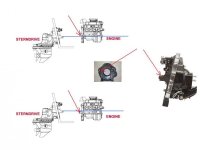
Shown as an extreme example:

Top image shows rear engine mounts as though too high above the inner transom plate mounting ears.
Lower image shows as though being too low.

You can see that this would throw the Gimbal bearing/shaft/coupler geometry out of whack.
 

Attachments

  • Merc rear engine mounts.jpg
    Merc rear engine mounts.jpg
    34.8 KB · Views: 359
Last edited:
RICARDO, IS THERE A NUMBER I CAN REACH YOU AT?
MINE IS 757-576-7867 TEXT ME A NUMBER IF YOU ARE WILLING TO TALK via PHONE WHILE IM AT THE BOAT BEATING MY HEAD AGAINST THE TRANSOM. THANKS
 
Welp I HAVE ACHIEVED THE PERFECT ALIGMENT!!!!!!!!!!!!!!!!
The tool slides in and out like a knife in a bowl of butter. I was told by two old salts, at seperate places, that the gimbal bearing has to be persuaided up down left and right with the smack of a hammer to the tool(i used my hand instead and a few choice words) backed up started over again and the S.O.B. slid right in.

Now i would like to also that you guys for your outstanding responses and patientce while explaining things to me.

Im sure ill be back with more ??????'s
 
Back
Top