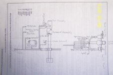
Have a 1982 40hp mariner/yamaha with external key switch wires, Got it for 225.00 heard it run via pull start, started right up. picked up a mercury key switch with push to choke. Wire colors dont match. I dont want to burn any thing up ,because it does run good. just want to be able to turn the key. Switch wires are red, black, violet, black w yellow , yellow w red, yellow w black.. 6 wires on key switch.. Now for the engine harness , red, black, yellow, green, blue, white, brown,. The harness has 7 wires. can anyone help me with this . I tried to follow the wires but got nervous, I would burn something up. Thank you .
Home
Outboard Motor Parts
Chrysler outboard parts Evinrude outboard parts Force outboard parts Honda outboard parts Johnson outboard parts Mariner outboard parts Mercury outboard parts Suzuki outboard parts Tohatsu outboard parts Yamaha outboard partsInboard & Sterndrive Engine Parts
Chrysler Marine inboard parts Crusader Marine parts MerCruiser sterndrive parts OMC sterndrive parts Pleasurecraft Marine parts Volvo Penta marine parts + MoreAll Engine Brands
All Manuals HomeOutboard Repair Manuals
Chrysler outboard manuals Evinrude outboard manuals Force outboard manuals Honda outboard manuals Johnson outboard manuals Mariner outboard manualsMercury outboard manuals Nissan outboard manuals Suzuki outboard manuals Tohatsu outboard manuals Yamaha outboard manuals
Inboard & Sterndrive Engine Manuals
MerCruiser sterndrive manuals OMC sterndrive manuals Volvo Penta marine engine manualsPlease Note
MarineEngine.com does not offer troubleshooting assistance or repair advice by email or by telephone.
You are invited to join our public Boat Repair Forum to seek assistance from other members.
You may also visit the Boat Motor Manuals section of our site to obtain a service manual.