Logo

1967 Mercury 50hp no spark condition

SaltyScot

Regular Contributor
serial # is 2214455

It was running good and then I opened the control box to fix the cables. Now it cranks, but doesn't start. No spark detected. I'm pretty sure it's corroded wires in the control box. I already fixed up the engine side of the wiring harness. I'm thinking the white wire(F). How do I test the white wire that comes through the harness and connects to the bottom terminal on the box? Should I get 12v when I crank it? I'm assuming that that wire carries voltage back to the motor in the start/run condition. Obviously I'm no electrical engineer. LOL Everything else seems to be ok through the controller, including the choke. I swear it worked after fixing the cables, but that was months ago and those wires looked pretty bad. I taped them as best I could. But who knows?

Stephen
 
I would start by checking/bypassing the neutral safety switch,the white wire is constant 12v+ while the key is switched on.
 
I had the shift lever off and it wouldn't even crank until I got it on and in the right position. Then it would crank. So I believe the NSS is working. But I definitely don't have 12V on the white wire. I'll have to cut out all the wires in the control box and rewire the switches. Thank you. That was the answer I needed.
 
According to my one of my manuals that motor has a magneto or an electronic driver ; do not put 12 volts on the white wire it is used to ground the magneto to stop the motor, on the electronic one the wire isn't white.
Any short between the white wire and the control box will short the magneto; the magneto generates its own spark with breaker points the electronic one does the same but generates a current that fires the switchbox.
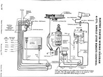
Check these wiring diagrams to decide which one you have.
4cyl-wiringsmall.jpg50hp wiring.jpg
 
Last edited:
The white as the kill circuit was pre '66,it went to salmon '66 according to the black and white diagram. And the number posted makes it '67,so I think it's safe to assume the coloured diagram is the wiring system.
 
The white as the kill circuit was pre '66,it went to salmon '66 according to the black and white diagram. And the number posted makes it '67,so I think it's safe to assume the coloured diagram is the wiring system.

I believe that’s correct, but I’ll have to check when I get home from work. Thanks
 
According to my one of my manuals that motor has a magneto or an electronic driver ; do not put 12 volts on the white wire it is used to ground the magneto to stop the motor, on the electronic one the wire isn't white.
Any short between the white wire and the control box will short the magneto; the magneto generates its own spark with breaker points the electronic one does the same but generates a current that fires the switchbox.
Check these wiring diagrams to decide which one you have.
View attachment 25261View attachment 25262
Definitely looks like the lower diagram
 
Go on-line and find CDI's website, then pull up their troubleshooting section on your motor. There's a test to determine if the trigger coil is shot and others.

Jeff
 
If it's the lower diagram with the Lightning energizer the tan wire that goes to the blue wire on the switchbox shuts off the motor, so does the tilt limit switch by grounding it.View attachment 25270I suggest disconnecting the wire and tilt switch at the switchbox and seeing if it sparks.
 

Attachments

  • lightning-energizerS.jpg
    lightning-energizerS.jpg
    178.4 KB · Views: 76
Last edited:
My plan is to start by repairing all the wiring in the control box. I’m going to cut the wires just off the ignition switch and extend the wires 3-4’ out of the box to mount the ignition switch remotely. Too many wires in too small of a space. Once it’s all shrink wrapped, it should work. But If it doesn’t, then I’ll start troubleshooting. Thanks again.
 
According to my one of my manuals that motor has a magneto or an electronic driver ; do not put 12 volts on the white wire it is used to ground the magneto to stop the motor, on the electronic one the wire isn't white.
Any short between the white wire and the control box will short the magneto; the magneto generates its own spark with breaker points the electronic one does the same but generates a current that fires the switchbox.
Check these wiring diagrams to decide which one you have.
View attachment 25261View attachment 25262
While it looks like the second one, there are a couple difs. The starboard side of the switch box colors are (from bottom to top) Ignition coil ground black, white, red, tan, and then the black from the coil. On the port side (from bottom to top) brown, white, and black. And I speak of the colors of the of the box, not the wires.

I replaced all the wiring in the controller and it turned out pretty nice. But still no spark.

I did try to remove the tan wire and got no difference. I don't see any blue wire, or blue block on the switch box. My ignition driver wires are not red, white, and blue. Everything else looks the same as the diagram. Maybe a different diagram?
 
You said this is a 50hp and those are the only systems for a 50; this diagram is for larger hp motors with battery charged Thunderbolt, the white wire has +12v to energize it;
75-850wiringsmall.jpg
 
Bingo. It was no 12v at the white wire. I ran a jumper to it and now I have spark. But now I need a new starter. DTOH! :eek: It cranks slower and slower every time I try it, even after frequently charging the battery.

It WAS that last diagram that you showed. The previous diagram(bottom) is identical to a 1971 50hp parts motor that I have in my garage.

Thanks Quicksilver!
 
Back
Top