Logo

What does "Bias" or Balance wire do between the 2 CDI switch modules?

Thrashercharged

New member
I have a Mariner Magnum II 150 / Merc XR4 2.4L that doesn't have spark in any cylinder. The trigger wheel and stator ohm out to spec. I've verified with a scope that the trigger wheel is good and the stator is outputting the correct voltage; it appears that both CDI Switch modules are dead. I find it odd that both are bad so if possible, I'd like to try to test each module independently.

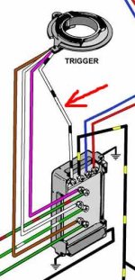
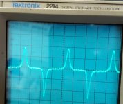
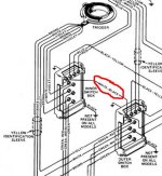
The pics show the scope traces of the trigger wheel and the white/black wire. On the V6 it connects between the 2 CDI switch modules and I've heard it referred to as the "Bias" or "balance" wire. On the 3 cyl with only a single CDI Switch, it goes up to the trigger wheel.

What's this white/black wire do exactly? I figure the modules are the same between the V6 and the 3 cyl, so it's puzzling to me how that same terminal can connect to the trigger wheel on the 3 cyl and between the 2 modules on the V6? I did disconnect the black/yellow kill wires and all wires look good.

Note: I posted this question on Bassboat Central earlier but figured I'd get a wider audience here and better chance of getting an answer!
trigger signal crop.jpg CDI Switch modules V6.jpg CDI Switch module 3 cyl.jpg
 
From what I know, your motor is like two, three cylinder motors (where the ignition system is concerned). The bias wire unites the two separate ignition systems.

Jeff
 
From what I know, your motor is like two, three cylinder motors (where the ignition system is concerned). The bias wire unites the two separate ignition systems.<br>
<br>
Jeff

Thanks for the response Jeff. I'm wondering how it unites those 2 separate systems. What sort of signal do those modules send across that wire? Or in the case of the 3 cyl engine, what signal does the trigger send down that wire? Does it ground it? Send some voltage level? Send an AC signal?

Basically, I'm wanting to test each module out independently of the other (just test one bank of the V6 at a time). Obviously I'll only test for spark and not actually run the engine. If I knew what sort of voltage level or signal the 3 cyl trigger is sending down that wire, I could mimic it and put a module into 3 cyl mode for testing.

Anyone know?
 
Last edited:
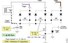
On a V-6 the bias circuit is used stabilize the timing between cylinder banks. There is a bias capacitor in box that applies negative voltage to the triggering circuit. If you lower/raise this voltage(advance/shift modules) the timing will advance/retard.( T=(RxC) ) As for your problem this bias might have killed a box but not both. Get a DVA adapter and check actual voltage output as ohms test can be deceiving. Here is basic operation...
bias.JPG
 
fazbullet - thanks for the technical reply! It's just what I was looking for. I looked at that diagram and I'm still a bit confused -

The diagram doesn't seem to show what the trigger common (white/black wire) is connected to? If it's GND, then the voltage on the capacitor would quickly go negative through the left side diode when the signal goes negative and (no resistance) charge back toward positive when the trigger is positive through the 30K ohm resistor.

It seems the 1K and 15K for setting the threshold to trigger the SCR and not part of the time constant? And Time constant = RC, not R/C (the diagram has it both ways). So lots of confusion over that diagram. It seems the circuit isn't quite drawn completely or just partially? It says page 72 on it, is this from a training manual? Is there more info or can you explain how the circuit functions?

Sorry for all the questions, just really trying to understand how this module works. As an aside, I bought 2 new modules and I have spark now, but I only get 1 combustion event and it almost seems like it fires at the wrong time and just stops the engine dead - the flywheel starter gear disengages. I'm thinking timing is off? I'll start a new thread for this. Thanks again for the help and technical info!
 
Last edited:
Back
Top