OneEyedWillyIsMyCopilot
New member
Hi everyone, I'm working on a friend's 1982 SeaRay 255 SRV with twin Mercruiser 485's. I'm trying to wire up the charging system, and I've run into a curious anomaly. I'm wiring the two charging systems in parallel, connected to a single isolator (Schottky diode type), which feeds two batteries (one house battery, one 'engines' battery). I know there are dual alternator isolators available, but this one is functional and came with the boat, and I'd like to make it work. Also in parallel with the two alternator outputs is an Intelli-Power PD9130 AC-to-DC converter.
The problem I'm having is, when wiring the system according to the Mercruiser #8 manual's instructions, I get approximately 10 volts on the input terminal of the isolator, meaning that somehow the isolator's diodes are being circumvented. When I modify the wiring slightly, the voltage is no longer present. I believe there is something internal to the regulator/rectifier units that would explain this anomaly, but without a schematic of the regulator/rectifer's internal workings, I can't pin it down. If anyone has such a schematic, or can at least verify that the latter wiring is acceptable, I would very much appreciate it.
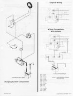
This is how the Mercruiser #8 manual recommends wiring the regulator with an isolator:

According to that diagram, the metal jumper between "Output" and what I assume is "Regulator" terminals is to be removed, with the "Sense" and "Regulator" terminals to instead be connected to one of the isolator output terminals (presumably to account for the voltage drop across the Schottky diode).
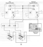
Following these instructions, this is how I have the system wired:

With this setup, however, I measure roughly 10 volts at terminal "A" of the isolator - when no input is present. When I remove the "Sense" wires from the output side of the isolator, the voltage disappears. This problem exists even when only one system is wired, so the issue is not related to running two systems in parallel.
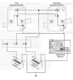
I decided to try wiring it back "stock", only moving the sense wires to the output of the isolator, but leaving the jumpers between "O" and "R" terminals in place. Here is a diagram describing this arrangement:

With this arrangement, everything *appears* to function as it should. The quiescent voltage at terminal "A" is no longer present.
I'm rather curious if the Mercruiser manual is just completely wrong, or if something is amiss. If anyone has any information, schematics, or advice; I would appreciate it tremendously. If nothing else, I would very much like to know if the last wiring method I described is acceptable.
Thanks in advance.
Edit: Here are links to larger versions of the images. The forum uploader appears to have resized the originals.
Mercruiser Wiring Recommendation
Problematic Wiring Arrangement
Presumably Functional Wiring Arrangement
The problem I'm having is, when wiring the system according to the Mercruiser #8 manual's instructions, I get approximately 10 volts on the input terminal of the isolator, meaning that somehow the isolator's diodes are being circumvented. When I modify the wiring slightly, the voltage is no longer present. I believe there is something internal to the regulator/rectifier units that would explain this anomaly, but without a schematic of the regulator/rectifer's internal workings, I can't pin it down. If anyone has such a schematic, or can at least verify that the latter wiring is acceptable, I would very much appreciate it.
This is how the Mercruiser #8 manual recommends wiring the regulator with an isolator:

According to that diagram, the metal jumper between "Output" and what I assume is "Regulator" terminals is to be removed, with the "Sense" and "Regulator" terminals to instead be connected to one of the isolator output terminals (presumably to account for the voltage drop across the Schottky diode).
Following these instructions, this is how I have the system wired:

With this setup, however, I measure roughly 10 volts at terminal "A" of the isolator - when no input is present. When I remove the "Sense" wires from the output side of the isolator, the voltage disappears. This problem exists even when only one system is wired, so the issue is not related to running two systems in parallel.
I decided to try wiring it back "stock", only moving the sense wires to the output of the isolator, but leaving the jumpers between "O" and "R" terminals in place. Here is a diagram describing this arrangement:

With this arrangement, everything *appears* to function as it should. The quiescent voltage at terminal "A" is no longer present.
I'm rather curious if the Mercruiser manual is just completely wrong, or if something is amiss. If anyone has any information, schematics, or advice; I would appreciate it tremendously. If nothing else, I would very much like to know if the last wiring method I described is acceptable.
Thanks in advance.
Edit: Here are links to larger versions of the images. The forum uploader appears to have resized the originals.
Mercruiser Wiring Recommendation
Problematic Wiring Arrangement
Presumably Functional Wiring Arrangement
Last edited:

