Logo

Trim and hydraulics - need some basics on how it works and what it does

prof_fate

New member
I'm new to stern drives - traded for a 75 crestliner 19' w/ mecruiser 165 and gm straight 6 engine.

Seller told me one of the trim lines is bad on the exterior and he just lifts the drive up manually when he removes it from the water. Of course I plan to fix it but will be giving the boat a 'float test' monday to find out why he was really getting rid of it.:eek:

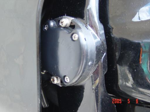
Anyway, got it home and went through it - low on hyd oil (20w motor oil?). So I found the pump, a servo of some kind, a stop switch that has been bypassed (wire cut). The servo looking thing has 2 wires, 2 hard plastic lines, and was stuffed in behind the wiring instead of being mounted to something - good sized steel bracket but I couldn't find anyplace it might go...I rigged something temporarily.

So what does the trim do besides lift/lower the drive unit? How do I trim it (button on dash, I know! :rolleyes:) but I guess, WHY do I trim during use?

And can I run it with a 'dead' hyd system?
 
There is a lock bar on the stern drive to hold it up while trailering. Looks well made - not sure if it looks 'factory' or not. The previous owner used it to lift/lower the drive unit and hold it up for trailering.
When I had an outboard I had a similar device to hold the engine up so at not to rely on the factory pin.

Manual link was very useful - Thanks!

Apparently the bypassed switch is the one that stops the unit when fully up for trailering. I can test it easily enough - wiring it back in should be fun..finding the right wires.

But then there is nothing so fun as messing about in boats, is there?
 
Last edited:
Ayuh,... If the Po didn't fix the broken line, I'd guess there'll also be a Water Intrusion issue to deal with too,...

The tilt/ trim system not only trims, 'n tilts, but holds the drive Down, in reverse,...
 
This may help:

How the trim/tilt works

Before you tear anything apart or replace wiring and switches, test it out; firstby visual inspection by pulling back and forth on the wires while operating theswitches and then test with a meter. At the commander switches ,the red wirewill always have 12 volts. The green wire gets 12 volts when the trim toggle isheld down. The blue wire gets 12 volts only when the toggle is held up or thetrailer switch is pushed in. The purple wire is part of the limit switchcircuit.

If the switch voltages are as they are supposed to be then go to the trim/tiltpump assy. and make sure the purple wire connector (single wire) and the bluewire connector with two blue wires on one side of the connection are notcorroded or loose. These are the trim position and limit switch wires. Pullthem apart and inspect; they should be clean and tight; reconnect them. Ifnecessary, trace the wires to the front of the engine near the slave solenoid.One wire is grounded near there and the other is connected to a terminal. Ifyou don't get a voltage reading at the terminal junction, apply 12 VDC to seeif the trim gauge moves. If it does, check for voltage back at the trim pumpconnections. If there is no voltage there, apply 12 VDC there to check gaugemovement.

Next check the three wire connector (RED, BLUE & GREEN) at the pump assy.This plug can vibrate loose and cause your problem. Pull it off and see if the pinsare clean and not corroded; reconnect it.

The RED wire in the plug sends 12 volts from the pump assy. to the toggleup/down and trailer up switches. The BLUE & GREEN wires bring 12 volts fromthe toggle trim/tilt and trailer switches to the two solenoids on the pumpassy.

The GREEN wire goes to the DOWN solenoid while the BLUE wire goes to the UPsolenoid.

Did you check the switches with an ohmmeter? The trim/tilt switch is a 2-wayswitch and will show continuity only when it is toggled in each directionbetween two of the wires.

Up toggle connects the RED wire to the BLUE wire. Down toggle connects the REDwire to the GREEN wire. The TRAILER UP switch also connects the RED wire to theBLUE wire.

The OD trim limit switch will only send voltage to the trim/tilt switch in theupward toggle position if the OD limit switch is below the adjusted trim limitthat keeps the OD being out of the water.

To test the limit switch circuit, lower the OD to the down position and slowlyraise it with the trim toggle up until it stops. Then measure the distancebetween the trim cylinder attaching bolts. If the distance is approx. 20 +/-1/4inches, then the trim limit switch is adjusted properly and the commander trimtoggle switch is working in the up/down mode.

Go to the trim/tilt pump assy. and make sure the purple wire connector (single wire)and the blue wire connector two blue wires on one side of the connection arenot corroded or loose. Pull them apart; they should be clean and tight;reconnect them. Next check the three (RED, BLUE & GREEN) wire connector atthe pump assy.The RED wire in the plug sends 12 volts from the pump assy. tothe toggle up/down and trailer up switches. This plug can vibrate loose andcause your problem. Pull it off and see if the pins are clean and not corroded;reconnect it.

The BLUE & GREEN wires bring 12 volts from the switches to the twosolenoids on the pump assy. The GREEN wire goes to the DOWN solenoid while theBLUE wire goes to the UP solenoid.

Disconnect the trim/tilt assy. wires from the battery and then check each ofthe nuts and studs on the solenoids for clean and tight fittings. Each solenoidhas three wires and the buss bar connected to it. The bases of them have ablack ground wire and a small blue wire to one and a small green wire to theother.

On top of each solenoid, the large BLUE wire from the pump motor attaches to alarge copper stud with the solenoid that has the small blue wire at the base whilethe large GREEN wire from the pump motor attaches to a large copper stud withthe solenoid that has the small green wire at the base.

The other copper solenoid studs are connected together with a copper buss bar.One of the two studs will also have a funny looking 110 amp fuse attached tothe bar. The large RED wire from the battery connects to the 110 amp fuse. Thislarge red wire is the power for this buss bar. A small RED wire attached to thebar stud sends 12 volts to the switches which in turn sends the 12 volts to thesolenoids which turns on the pump motor.

Important: if the studs on the either solenoid are dark and not like a cleanpenny, especially the BLUE wired solenoid, this solenoid is failing due to ageand/or a loose bottom copper stud nut. The dark color comes from heat generatedinside of the solenoid by the contactor because it is arcing like weldingsimilar to points wearing out. Change the solenoid.

Cleaning Trim Limit Switch & Trim Position Sender

For the trim/tilt, if the wires from the limit switch (port side) and trimposition sender (starboard side) are in good condition, they (Switch or sender)can be disassembled to clean out the old hardened grease. SCRIBE the sides ofeach one and the OD for a reference mark before removal. Clean out the oldgrease and pump fresh Mercruiser 2-4-C grease thru the zerk fittings beforereinstallation. Clean the small brass contact points with solvent and a pencileraser until shiny; repack w/ 2-4-C grease and reinstall by aligning reference marks.

 
The resivour is low but not milky, nice and clean actually.

I figured it would hold it down in reverse so gonna replace the line before venturing out.

Thanks for the trim info - I'll put it to good use!
 
OK....I'm not finding the part on my boat in the manual (referenced earlier).

I have power trim. That I've found - the pump and solenoid.
I have two other things plumbed into the system though - and one is leaking!

There is what appears to be either an actuator or perhaps a sensor (the item that was just stuffed in behind the cables) and from it are two hyd lines - one to the pump and the other to the leaking device...

Which is part of the gear shift linkage assembly on top of the transom plate. When the gear lever (cable actuated) is moved this device moves - and leaks.
It has 2 light blue wires to it and a limit switch - the 'disconnected' switch I mentioned earlier seems to be a reverse cut out swtich (mounted by itself far port side of the transom plate).

I need a name for this device so that I can get parts or get it replaced. Not sure what it does exactly either.

EDIT - looking around a mercruiser parts site it's apparently a reverse lockout valve ass'y.

Help me out - how/what does all this stuff do?
trim I got - up and down on the drive unit.
I'm used to simple gear - fwd/reverse and neutral of course.

What does this hydraulic unit and the cut out switches do?
Does the pump run continuosly or only when needed (and if it does more than trim, when does it run?)
 
Last edited:
Let us know what model / SN's are for the engine and drive unit.

Did you read guyjg's #5 post? Did you read the manual? Try this link. Should be same as yours: http://www.boatfix.com/merc/Servmanl/6/6C5R3.PDF

1. There should be no "reverse lockout valve assy". I suspect you are describing the limit switch for the trailer position of the lift cycle of the system, shich should be on Port side of gimbal.
2. The two "sensors" on the gimbal are the "position" sender (stbd side of gimbal) to the gauge and "limit" switch (port side of gimbal) to the control wiring. These are in the circuits to the trim pump / switches / trim gauge. Wiring schematic is in the manual. There should be no other switches / sensors / valves in the engine compartment seperate from the pump assy (which includes pump and relays mounted on the bracket).
3. Pump only runs when buttons are manually pushed.

The items you are trying to describe don't make any sense at all. Perhaps some pictures will help.

If you can lift the drive unit by hand after it's on the trailer, the trim system has some serious problems. relating to the trim pistons and / or pump valves, which I would venture to say are toast. If you can lift by hand, when it's put in reverse the drive would lift immediately.

If there is a "reverse lockout valve", I would think it's something the PO added because the PO didn't know how or was too "frugal" to repair properly and Mickey Moused to almost make it resemble to work. And I would suspect there may be other issues that were "moused", as well.

Have owned a few Mrecruiser's on various years, sizes and models, and none had anything you are trying to describe.

I would venture to say that the entire hydraulic system needs to be re-done, as it sounds like it has been Mickey Moused / neglected beyond being usefull for the intended design / purpose.

The Mercruiser tilt / trim system actually works well, is quite simple and robust and only needs minor maintenance to work problem free for years. (My current one is 22 years old)
 
Last edited:
Well....this IS on my boat - and you can see the name of it - "reverse lockout valve assembly"
http://www.marineengine.com/parts/m...3442-thru-4890459/reverse-lock-valve-assembly

It bolts to the top of the transom plate, sitting horizontally and is bolted to the throttle cables and as they move this valve moves. At one end the switch is activate breaking the circuit. This is on the starboard side above the pump. On the same plate on the port side is another limit switch that appears to do the same thing but for the other direction (an assumption at this point)

I've got most of it apart and some parts are not available - like the main shaft that runs through it that the PO over tightened and stripped the threads trying to stop the leak.

As for being able to lift against the cylinders..with no pressure in the cylinders - probably no fluid at all - of course they'll move easily.

Here is a drawing of the components. The dashed lines are the pump on the left, the valve in question on the far right and what I think is the tilt sensor (looks diff in this pic but the specific pic/page matches what's on my boat).
23.gif
 
The OP has a 1975 Mercruiser 165.

The drive position sensor is very likely what the OP mentioned as a "servo of some kind".


I believe that he's referring to older the Merc 165 style.


Note that the 165 gimbal ring does not have the sensor nor switch on either side of it.


The link posted for the PDF file is for a later Merc drives that use the gimbal ring located trim indicator sensor and limit switch.


Point being.... the trouble-shooting info in the PDF file may not be accurate for his use.
 
Last edited:
The answer to your problem is to look on craigslist or ebay and buy a newer model with the reverse lockout biult into the pumps valving.

Then you will simply have two lines feeding the trim rams eliminating the lockout valve all together.

http://www.ebay.com/bhp/mercruiser-trim-pump

Just make sure it is one with the lockout valving in the pump assembly.

All trim pumps with the plastic resevoir have the lockout valve internal. The ones with the solid black resevoir it is hard to tell unless stated in the sellers description.

Then wire it to the alpha one gen 1 specs......
 
Thanks for the info.
Went to the local boat dealer to transfer title and get registered - got the line to the ram (used) and by then I'd figured out the issue with the lockout - there is a wave washer in the bottom that applies pressure to the center shaft bolt to take up the slack - it was installed upside down, plus the valve body top was installed 90 deg off. Proper assy seems to have fixed the issue - I just need to deal with the party stripped shaft (stud actually so in theory could be changed out) on the top part. I think I can space out wiht a washer and use the top part of the threads that are still good.

The transom is soft around the stern drive mount but that's an issue for spring - I just want to identify any other issues ASAP so I'm prepared for what is to come.
 
Went out for a 'sea trial' yesterday.
when I hooked up the reverse lockout as it was the wiring was wrong, so I did some studying and got the sterndrive to go up and down with the buttons. I left the lockout switch disconnected.
I'll have to study a bit more and wire it in - anything above idle in reverse and the sterndrive climbs out of the water. Not sure what the hydraulic bit does but is seems the switch will power the 'down' side of the pump. At least that's how I'm wiring it.

Had 2 issues that were unexpected. The bilge pump runs but pumps no water out of the boat. Since the transom needs a repair that's an issue as the boat does take on some water. Not sure what I did - saw the pump function when I looked at the boat. Should be an easy fix.
The other is idle speed..not sure if it's high or not but getting docked and and back on the trailer was a challenge. Too fast in gear and take it out and no steerage at all. A bit of practice might help but it was dead calm and no boats making waves so in less than perfect conditions it's gonna be a challenge.

Overall it was fun and successful. Total cost for repairs was under $30 and a few hours of time.
 
The reverse lock out "switch" should have a hydraulic line running thru it, correct?

If it does then the "switch" hydraulically locks out reverse to stop exactly what you are experiencing...........The electrical part of the reverse lock out (switch with wires) appears to be there so you can not activate the pump in the up direction at the same time as the hydraulic lockout is activated and over pressurize the pump or lines.

Replace the bildge pump........new is better than old..........or you may sink........

Idle speed should be ~ 650 rpms in gear (putting along). anything higher than 750 rpms will create issues of many kinds.

when the boat is underway (motor running and in gear) the skeg of the lower unit (bottom of outdrive) and the outdrive itself is what steers the boat.

when not under power (in gear) the steering is comprimized as no propulsion is occurring.......difficlut to control steering especially at low to no speed.
 
Back
Top