Logo

LED Indicator wired incorrectly?

gtorresucf

New member
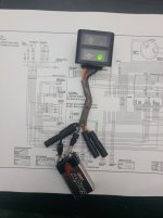
I have a Honda BF30. I am troubleshooting why the oil pressure indicator lamp never turns on. Motor runs fine, no LED and no Buzzer. With the engine off, I removed the yellow wire from the oil pressure switch and with an ohm meter, from where the wire connects, there is continuity to ground. Is this correct? I also checked the complete continuity path of the yellow wire from the switch to the CDI and the CDI to the lamp indicator, all good. I then tested to see if the actual LED lamp was good. I removed the Indicator assembly and placed a 9V battery to the Yellow and Red wires, no lamp. I then placed the 9V battery on the Black and Grey wires, and to my surprise, the Oil Lamp indicator lights up Green. How can this be? According to the wire diagrams I have seen, the Yellow and Red wires are for Oil Pressure, and the Black and Grey wires are for the Over Temp sensor. Any guidance would be much appreciated.
 

Attachments

  • ATT00001 (68).jpg
    ATT00001 (68).jpg
    863.2 KB · Views: 4
Hi,

I don't have any experience with the BF 30 so I'm just speculating here.

But I do think that the oil pressure switch is normally closed (NC) and provides ground to the yellow wire with engine off.

When the engine starts and builds oil pressure, the pressure switch goes open and removes ground allowing the CDI to provide power to the lamp assembly. At least that's how it works on my BF20D.

The question I have, after looking at the photo you provided, is do you have the correct lamp assembly for your outboard? The schematic you have doesn't match up with the lamp's pigtail.
It's hard for me to make out because the photo blurs when enlarged but it appears to me that the schematic shows a black/yellow (Bk/Y) wire and no Gray (G) wire.

Does your outboard wiring match up with that schematic?

Or, does your outboard wire colors match that lamp assembly pigtail's colors?

IF...
...your outboard and that schematic match then...
You likely have the wrong lamp assembly.

We know black is ground so you might try running the engine with the lamp unplugged and check if there are 12 volts at the Bk/Y wire after oil pressure builds up. If so, you may just need to connect Bk/Y on the engine side to G wire on the lamp harness and drive the bulb like that.

Just a guess.

Good luck.
 
Thanks for your input. The schematic I have posted is for the large tiller version. I downloaded the Remote version and the pigtail is correct. I was experimenting around and I think I found that the red wire is actually a the Thermal signal (-) from the CDI and the yellow is the Oil Pressure signal (-), also from the CDI. When I apply the battery to GRY and BLK wires, the Oil Pressure indicator turns Green. I ground the yellow wire, the correct lamp turns off. I also tested the oil pressure switch and found that the statement from the previous post is true. It is a normally closed switch and as pressure builds, the switch opens. If I ground the Red wire, the Temp Overheat lamp turns on. Turns out there is more to the Lamp assembly than a couple of LEDs. Turns out, I wasn't getting a 12V on the BLk/Y wire, which I believe is the accessories switch. No 12V to the Lamp assembly and buzzer. I pulled the ignition switch and tested for proper operation. The contact was flaky when tested in the ON position. Looks like I'm replacing the ignition switch.
 
Oh! Well, GOOD HUNTING then!

Glad you worked it out.

Please update after you get the switch replaced and let us know how it went.

Thanks for the explanation and welcome to the forum!
 
Back
Top