Logo

Help - Where to install heater water lines?

I got a heater for my boat from Heatercraft. I finished al the installation but got stuck on the water lines.

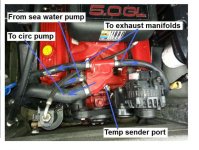
I have a Volvo Penta 5.0 GL-H engine (2007)

I first tried to connect the lines to the ones going to the manifold but they were not getting hot... then I connected one at the engine drain plug (bottom back) and another one to the manifold (bottom back as well). I removed a plug on both of them and connected the lines in there.

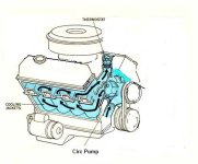
I managed to get hot water quick however I noticed that the thermostat housing was not getting any hot at all and it was not showing the temperature properly.

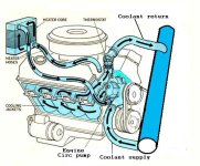
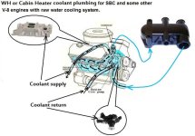
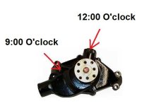
Question: Where should I be plugging the lines? If possible, I would appreciate if you could point a bit more precise on the location instead of the way the manual says like: Plug on top of engine manifold and Plug on the water pump housing.

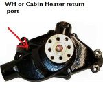
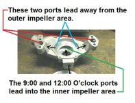
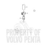
I couldn't find anywhere to plug on top of the manifold ... and on the water pump I see a big red plug on top of it and the alternative I thought was to remove the thermostat, put a T in place and plug the thermostat back on the T and the line in there.

All help very much appreciated.
 
The 5.0 GL is a SBC engine.
This should be your intake manifold. I see that there is no 1/2" port, so you may need an adatper/spacer underneath the T-stat housing.

Whether Raw Water cooled, or a Closed Cooling system, you will be taking your "supply" from just prior to the Thermostat.
Not from the heat exchanger, nor from the exhaust manifolds.

Here's why:

We need to create a pressure differential between the Heater supply and the Heater return.

The engine circulating pump is charging the block with coolant.
The thermostat is holding back this charge.... (aka coolant).
So in essense, the block is under mild pressure when the engine is running.

When we supply from a port prior to the thermostat, we are within this mild pressure zone.

As for the return.... we want this to be in the starboard most 3/4" port of the circulating pump.
This is within the suction side of the cooling system.

Now we have a balanced system. Both a mild pressure suppy, and suction return.

NOTE: most people who end up installing a 12 vdc "puppy pump", do so because they have not followed this simple basic plan.

This image reflects a Closed Cooling system, but the RWC'd engine plumbing would be the same.
If RWC'd, your heater core now needs to become part of your winterizing.
 

Attachments

  • SBC cooling-system.jpg
    SBC cooling-system.jpg
    46.4 KB · Views: 35,661
Last edited:
Thank you Ricardo... Very helpful... If you don't mind, I will post a picture as soon as I get home to get your confirmation on the locations.

The 5.0 GL is a SBC engine.
This should be your intake manifold. I see that there is no 1/2" port, so you may need an adatper/spacer underneath the T-stat housing.

Whether Raw Water cooled, or a Closed Cooling system, you will be taking your "supply" from just prior to the Thermostat.
Not from the heat exchanger, nor from the exhaust manifolds.

Here's why:

We need to create a pressure differential between the Heater supply and the Heater return.

The engine circulating pump is charging the block with coolant.
The thermostat is holding back this charge.... (aka coolant).
So in essense, the block is under mild pressure when the engine is running.

When we supply from a port prior to the thermostat, we are within this mild pressure zone.

As for the return.... we want this to be in the starboard most 3/4" port of the circulating pump.
This is within the suction side of the cooling system.

Now we have a balanced system. Both a mild pressure suppy, and suction return.

NOTE: most people who end up installing a 12 vdc "puppy pump", do so because they have not followed this simple basic plan.

This image reflects a Closed Cooling system, but the RWC'd engine plumbing would be the same.
If RWC'd, your heater core now needs to become part of your winterizing.
 
Thanks again for the answer Ricardo... I took pictures in here of the thermostat housing with the connections to the manifold.

I had tried connecting before the "supply" line to one of the ports going from the housing to the manifold and the return line going to the manifold. (see picture). This is a 3/4 hose. Are you suggesting that I connect the "supply" to the other connection that has a larger hose? Sorry for the confusion, there is a lot of input lines and plugs and instructions are not very clear.

Here is the picture of it.

20130421_131349.jpg

That port will not work as a supply!
The two threaded ports, and the one large port in the circulating pump, are all suction!

.
 
Your 5.0L GL is raw water cooled. Even while raw water cooled, there are essentially two sides to the cooling system.
1... the sea water side.
2... the coolant side.

While this is sea, lake or river water at all areas, once within the engine we can refer to this as either "sea water" or "coolant".

Engine cooling demands are never equal to the amount of sea water supplied. Most all sea water is being diverted and sent to the exhaust system after having removed engine heat.

The Raw Water cooled engine T-stat housing doubles as a mixing chamber.
(see first image)

Speaking strictly of the engine coolant...... the circulating pump charges the engine block with this coolant.
The thermostat is holding this coolant back until temperature dictates.... and even while the thermostat opens, a large portion of coolant is still being held back.
While the coolant is being held back, it becomes mildly pressurized.
We take advantage of this mild pressure by using it as our cabin heater "supply" source.
(see image #2)


Meanwhile, the circulating pump is trying to pull more coolant back in.
(see image #2 again)

We take advantage of this suction by using the starboard-most port as our heater coolant "return".
(see image #3)


Now.... your intake manifold is minus this port that many other SBC Marine Engines have.
(see image #4)

I'm not sure what your options are!
Possibly a ported spacer that would install underneath the T-stat housing.
Or.... remove the temperature sender, and "T" into this port.


OK... image #5.
Don't let this image confuse you.
I drew this up to explain a rather risky winterizing procedure that some people attempt to use.
Where you read " -------- = sea water path (or antifreeze)" would apply to your engine only if the "(or antifreeze)" was omited.

Both T-stat housing mix and direct water in the same fashion.
The one to the left is a later Volvo Penta version, the one to the right is an earlier Volvo Penta version.

Read the color codes, and you will be able to see the path and temperature changes that the sea water undergoes.

Bottom line..... if you do not take advantage of the pressure differential, your cabin heater will very likely not work correctly.
 

Attachments

  • RWC T Stat housing.jpg
    RWC T Stat housing.jpg
    14.4 KB · Views: 345
  • Raw water cooling T stat housing explanation.jpg
    Raw water cooling T stat housing explanation.jpg
    63.8 KB · Views: 2,494
  • SBC Circ Pump.jpg
    SBC Circ Pump.jpg
    16 KB · Views: 602
  • SBC cooling-system raw water 4.jpg
    SBC cooling-system raw water 4.jpg
    59.7 KB · Views: 18,671
  • SBC cooling-system rwc 2.jpg
    SBC cooling-system rwc 2.jpg
    29.6 KB · Views: 11,787
This breifly explains your existing system.

Note where the temp sender is installed. In terms of flow, this is "up-stream" of the thermostat.
Schematically, this would be the same as what is shown in image #4 above.
 

Attachments

  • Raw water cooling T stat for ME com .jpg
    Raw water cooling T stat for ME com .jpg
    81.3 KB · Views: 2,766
Cant you just use the continuous bypass tube and make a loop wont that have both the posative and suction pressures using engine temp at the thermostat? Measure the temp of the bypass tube if it stays hot when the engine is up to temp couldnt you just use that.
The SBC does not use a by-pass as does the BBC or Ford 460.


Ok I read closer it says housing where continuous bypass occurs that goes back to what ricardo said maybe there is an adaptor plate to add on the heater lines?
The continuous by-pass that I'm refering to has to do with the mixing that occurs within the T-stat housing (raw water cooling ONLY).
Any WH or Cabin Heater supply must be taken from "Up-Stream" of the actual thermostat location.

I believe that there is a ported spacer that I've seen before, but quite frankly I don't recall which Marinizing company used it.
Basically, it raised the thermostat up, and offered a port that would be perfect for a WH or Cabin Heater supply source.
Nothing to the system changed except for the added port.


.
 
Last edited:
http://www.volvopentastore.com/Hot-...on_id.817941161--store_id.366--view_id.780940 This says hot water outlet seawater cooled I bet it is the pressure side for a heater
Probably a typo.

All three ports..... the large suction hose port, the port @ 9:00 O'clock and the port @ 12:00 O'clock, all lead into the center area of the centrifugal impeller. These are all on the suction side. If you look closely, you can see it in the casting.

Only the the two ports that mate and connect to the engine block, lead away from the outer area of the centrifugal impeller. These two ports are charged with pump coolant pressure.


Attachments

  • SBC circ pump interior view.jpg
    SBC circ pump interior view.jpg
    45.6 KB · Views: 367
Last edited:
You were absolutely right. There was a plug on the pump at 9'. It was difficult to access but I managed to get it out. For now I will connect the "supply" to a T connector I installed where the thermostat is but I will look for a more permanent solution.

Thanks again for all the help.

This breifly explains your existing system.

Note where the temp sender is installed. In terms of flow, this is "up-stream" of the thermostat.
Schematically, this would be the same as what is shown in image #4 above.
 
You were absolutely right. There was a plug on the pump at 9'. It was difficult to access but I managed to get it out.

For now I will connect the "supply" to a T connector I installed where the thermostat is but I will look for a more permanent solution.
Not where the thermostat is!
You'll want to tap into the port where the "Temp Sender" is currently plumbed into.


.
 
Hey Rick,

Just to update on my installation.... there was not enough pressure from that temp sender... run the engine till it was on regular running temperature (160) and heater wasn't getting warm neither I could feel the hose at the heater side warm.

I was given another option which was to plug where another temp sender is... it looks like a plug, just under the hose from Sea Water on this picture
Raw water cooling T stat for ME com .jpg


I tried plugging in there however same thing, run the engine for a while and heater doesn't get warm neither I feel the hose at the heater end warm and now even though the engine gets warm the temperature on my dashboard does climb up.

I'm running out of options. Never thought it would be so difficult to find the connection points on the Volvo Penta and vendor was pretty much useless.
 
Last edited:
The fitting at 12 oclock on the water pump says hot out saltwater cooling?
Kim, all due respect, that is incorrect. I cannot explain the error...... probably an over-sight that was not caught.

Both of these threaded ports in the circ pump lead into the suction side.
(see posts #7 and #8 again...... the disassembled pump view in post #14..... and the image below)

Look at this casting below.
You can see in the casting where each of the two ports direct coolant to the interior of the centrifugal impeller area.
These both lead into the suction side of the pump.
Only the two cylinder block mating ports push coolant into the engine block..... (I.E., the pressure side)
20057_L1


Look at the BBC by-pass connection. The SBC and BBC Circ Pumps are very similar.
The by-pass leads to the 12:00 O'clock port in the circ pump.
The intake manifold cross-over chamber is under mild pressure.
The by-pass dumps a small portion of coolant back to the Circ Pump.

If the 12:00 O'clock port was pressurized (as per what the Volvo Penta image suggests), the by-pass would not funtion..... since both would be considered to be under pressure.


Side note: Depending on who manufactured the circ pump, not all castings are the same.
On the pump above, it would appear that both of these are well ported.
On average, the 9:00 O'clock port is more commonly found to work best for the coolant return port.

.
 
Last edited:
Fransciso Fred, see posts #7 and #8 again. It's all explained in those posts.

I can't remember how many of these that I've plumbed this way, and they have all worked very well.

Let me attempt to explain this again:

The engine circulating pump is charging (or pushing) coolant into the block, around the cylinders, up into and through the cylinder heads. Once it leaves the cylinder heads, it is directed towards the intake manifold cross-over chamber.

The thermostat holds this coolant back until the correct temperature is achieved.

Because the thermostat creates resistance, mild "positive" pressure builds within the engine block/heads.... not much, but nonetheless, it is mildly pressurized.

We take advantage of this mild pressure by using it as our "supply" for a WH or Cabin Heater.

Since the intake side of the Circulating pump is pulling....... this becomes a "negative" pressure.

So.... with Positive pressure on one side.... and Negative pressure on the other side, we can now have a "balance" and coolant flow to/from and back again.


Here is the coolant path if everything is working in harmony.
This shows a Closed Cooling System.... but it's not unlike the Raw Water Cooled system re; WH or Cabin Heater plumbing.

Note that the coolant's means of escape (i.e., to exhaust and/or return to the circ pump) is via the thermostat, and is predicated by the thermostat's open position.
The other means of escape, is via the supply port, which is "up-stream" of the thermostat.
attachment.php


attachment.php


attachment.php


In a rather strange example, think of your home forced air heating system.
Your furnace fan pushes the warmed air thoughout your home.
But in order to be balanced, the return air ducting is required to bring this same air back to the heat exchanger.

If we do not plumb the WH or Cabin Heater correctly, it would be like your furnace without the fan operating.
(yes.... that was a rather silly anology)


Bottom line.... we need the pressure differential between the two sides..... or what I'm calling a "balance".

With the correct differential, we end up with a mild positively pressurized "supply", and a mild negatively pressurized "return".

This differential is what creates the coolant flow to and from a WH or Cabin Heater.

.
 
Last edited:
Added text:

The engine circulating pump is charging (or pushing) coolant into the block, around the cylinders, up into and through the cylinder heads.
Once it leaves the cylinder heads, it is directed towards the intake manifold cross-over chamber where it comes up against the thermostat.

The thermostat holds this coolant back until the correct temperature is achieved.
As temperature is achieved, the thermostat begins to open.
Under normal operating conditions, the thermostat will never open enough to allow more coolant to escape than what the circ pump is capable of supplying.


This is why this works so well as a "supply".


.
 
Last edited:
What your telling him to do is not working with all due respect we are just trying to make it work it may be a typo or an oversight but it may work it wont hurt to try will it?

Kim, are you suggesting that the 12:00 O'clock port becomes the "supply", and that the 9:00 O'clock port becomes the "return"?????

IOW, as per this Volvo Penta image where they show using fitting #4 in the port directly below it?
attachment.php


If so..... please explain how we could possibly get a supply and a return when both of these ports lead into the suction area of the circ pump?

attachment.php


Iwas just thinking you will want the water to drain completely out of the heater core and hoses when not in use with a seawater cooled engine to protect fromfreezing just something to consider when setting it up?
This we agree on!
I believe that I mentioned this to him earlier.


.
 

Attachments

  • SBC circ pump ports.jpg
    SBC circ pump ports.jpg
    20.8 KB · Views: 6,320
  • Volvo Penta circ pump plumbing error.jpg
    Volvo Penta circ pump plumbing error.jpg
    12.8 KB · Views: 5,788
Last edited:
Fred, the copper "T" fitting (installed in the large circ pump suction hose) will work in lieu of using the 9:00 O'clock port.
But I'd have to ask you....... why would you use one, when the 9:00 O'clock port is available, and is threaded for the correct barbed hose fitting???

attachment.php


Make your supply just ahead of the thermostat, and make your return in the 9:00 O'clock circ pump port, and your WH or Cabin Heater system will work.

I probably pulled my first SBC circ pump apart back in 1966, or so. I've not have a system like this fail to function since then.


.
 
Last edited:
I may be get confused in here... the 9:00 O'clock port is the one I plugged the return... isn't this hose #8 going to the circulation pump and would be a supply?

Anyhow, I got a tip today that I will try... I was told that there are a couple reasons I may not feel the hose at the heater end getting warm... I was told that I may have air trapped in there therefore it won't pump water through the heater and also that I should check if the connections on the heater aren't inverted... I thought that it wouldn't matter but I was told it matters, that I should connect the feed in the bottom and the return on the top.

I will check the connections and will disconnect the bottom hose and will blow water through the top hose to make sure I clear any air trapped in there.

Comments?

Fred, the copper "T" fitting (installed in the large circ pump suction hose) will work in lieu of using the 9:00 O'clock port.
But I'd have to ask you....... why would you use one, when the 9:00 O'clock port is available, and is threaded for the correct barbed hose fitting???

attachment.php


Make your supply just ahead of the thermostat, and make your return in the 9:00 O'clock circ pump port, and your WH or Cabin Heater system will work.

I probably pulled my first SBC circ pump apart back in 1966, or so. I've not have a system like this fail to function since then.


.
 
I may be get confused in here... the 9:00 O'clock port is the one I plugged the return... isn't this hose #8 going to the circulation pump and would be a supply?

Anyhow, I got a tip today that I will try... I was told that there are a couple reasons I may not feel the hose at the heater end getting warm... I was told that I may have air trapped in there therefore it won't pump water through the heater and also that I should check if the connections on the heater aren't inverted... I thought that it wouldn't matter but I was told it matters, that I should connect the feed in the bottom and the return on the top.

I will check the connections and will disconnect the bottom hose and will blow water through the top hose to make sure I clear any air trapped in there.

Comments?

Does the heater have a check valve installed? I don't have a heater, but my water heater has a check valve on one side, so if I were to reverse the lines, I would not get any flow. I remove and drain mine ever year, and have never had a problem with air in the system. But I do have an open loop system.
 
A check valve is not necessary. In fact, the resistance of a check valve may hinder the coolant flow.

If you want a valve (in order to prevent unwanted ambient cabin heat in the summer), install a ball valve in the supply.
 
Back
Top