Logo

Electro Mechanical Lift Aquamatic 250

jeffnick

Regular Contributor
Is there supposed to be an automatic stop circuit for up and down on the 250 drive? I know when the drive is all the way down because the red warning light goes out, but when bringing it up there's no way to tell when it's at the limit except to watch the voltmeter tank.

Things look fine inside the electrical box...
IMAG0223.jpg
 
If the 250 is like the 270 in this regard, there is no easy way to tell when the drive is all the way up. I have learned to carefully listen as it is being lifted as I can hear a difference when it gets up to a certain point, then I just do another few clicks of the switch and it usually is all the way up. Or if I have someone nearby, I have them tell me when it is all the way up. I tend to err on the side of caution so as to not strain the lift motor by keeping the switch engaged if the drive is already fully tilted up. Those motors can get expensive.
 
Jeff, the lift unit that you show is later than the 250, of which is good.
The original 250 lift out unit used the old Electrolux motor and older controler unit.

There will be a plunger style micro switch (the gray switch shown) that cuts the negative current to the motor when the vice rod fully retracts (drive down).
This also provides the negative for the amber light.

As for extending the vice the rod (drive up), the only means of knowing when the drive is fully raised, will be when the drive clutch unit slips.
When it does, the motor will change tone some.


To extend the life of your drive shaft bellows, try lifting the drive no further than need be.

BTW, your transom shield is not a 250 either. It will be either a 280 or a 275.
 
Last edited:
Jeff, if you do have a 250 drive connected to a 280 transom shield, no harm/no foul.
The 250 transmission is small bearing.
It connects to the 250 Intermediate housing ONLY..... meaning that a replacement MUST be a 250.
The lower unit will use bevel cut gears.... not hypoid.
All AQ series (in this style) lower units will interchange with the correct shimming procedure being done.

Here is how you'd tell;

The 250 Intermediate will have a fill plug just below the shift cover...... SEQ #31 and #32.
It will also have the insert SEQ #36 in the suspension fork...... later units have the hole only.

http://www.marinepartseurope.com/PentaPictures500/5972.jpg

All else will appear to be very much the same, until you get inside.

.
 
The boat is 40 years old, so who knows what is really on there. Maybe you can tell me more from some more pics. I did have the drive off and totally resealed (by a Volvo Dealer) and the motor out for fuel tank work. I had the intermediate bearing renewed before I put things back together.
IMAG0983.jpg


I know the middle section of the outdrive is not original. It looked to be much newer and the exhaust port was clean as a whistle when I pulled the drive off. The motor is said to have less than 20 hours on it - I have the work order for when they dropped in the new 260A - maybe there needed to be modifications to the drive/shield to take the new motor, or maybe it was a totally different repair?

IMAG1056.jpg


It looks a lot better cleaned and painted.

IMAG0242.jpg


IMAG0244.jpg


IMAG0224.jpg


IMAG0698.jpg
 
I just assumed it was a 250 from the badge on the cover. And as far as I can tell, there are no oil fill ports (not even under the cover). I think you're supposed to remove one of the bolts on top? I made a fitting to fill from the dipstick hole via a short tube so the breather doesn't choke. I know it's important to keep the level correct. I did pick up another supposedly good 250 along the way (for $80). It's a 4 cyl ratio but I thought I would tear into it to keep from being so scared of these new to me outdrives. You guys sure have been a comfort for me. The shops around here won't touch these old drives. It was tough finding a shop to reseal it for me.
 
You have a mixture of components there.
Judging from the colors, here's what has happened:
Someone has replaced the Intermediate with a later Intermediate.


That Transmission being a PZNR 25...... dictates that it is a 250.
The "D" says that it was originally behind a 4 cylinder.... of which is OK.
However, the "D" lower ratio (2.15:1) will be terribly incorrect for your V-8.
You MUST have the 1.61:1 ratio!


The Intermediate housing is later than a 250 (noted by the absence of the fill port).
The suspension fork is a 250... possibly early 270...... I can tell you this for certain!

I'm not comfortable with a 250 fork behind a V-8 due to that insert.

The 250 transmission uses a rather small diameter male yoke shaft..... and again, I'm not as comfortable using a 250 behind a V-8.

This trans should NOT be on that Intermediate housing... PERIOD!
I'll double check this for you..... but I do not believe this can be properly shimmed to this Intermediate housing.
The bore in the Intermediate is for the next size increase, and will be incorrect for the 250 driven gear bearing retainer diameter .
If not shimmed correctly, you risk case and bearing damage... possibly even gear damage.

Making an assumption here..... if they missed getting the transmission shimming correct, what/how do you think they did when installing the 250 lower unit onto this newer Intermediate housing???????
This too must be shimmed correctly, and this is a Negative pre-load, not Positive!


If this is the same shop that replaced the PDS bearings, I'd question their ability, and I'd want to know exactly what/how they did this, and whether they installed "sealed" or "open" bearings.
Ask if any Chinese bearings were used.
I'd also want to know if they "Pre-Filled" the grease cavity within the Flywheel Cover (aka Bell Housing in the auto world) prior to finishing.

These are important.... and need to be asked of them!


Jeff, for the very same reason that you found it difficult to locate a shop, people from all over ship these to me for this type of repair.
USPS flat rate box....... $16 X's two ways.... done.
Just an FYI on that!

.
 
I'm pretty sure the ratio is 1.6. I counted turns when I had it off. She won't plane - WOT 4,200 rpm nets only 14 mph with the old 15p prop and you can tell she's really working. I would expect her to rev much higher if the 4 cyl ratio was being used? I've moved the trim pin to the closest hole to see if that will help get her up and have a new clean 15p prop. Will test in 2 weeks. The literature says she'll do 28 mph; we're not wanting to go that fast and are quite happy at 7mph but it would be nice to know she can go faster.

The shop that sealed the drive was not the same one who put in the 260A. There was no mention of inconsistencies when the drive was resealed. I believe the reseal and intermediate bearing were done correctly but what happened prior is anyone's guess.


What can you do for me to make this setup correct? What drive will fit and what do you recommend? Do you have one or can you make mine work?
 
Well, I'd first recommend that the components be varified as to the correct interchangeability and correct shimming.
If they missed the issue of the 250 -vs- the later components, they may have also missed something else.

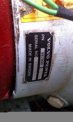
NOTE: Again, the PZNR tag on your transmission clearly says that it is a 250.
All 250's use the small (3.345" OD) driven gear angular contact bearings..... period!

NOTE: Any Intermediate that does NOT have the fill port, is the next generation for the mid-size (3.545" OD) angular contact driven gear bearing.

These two components should not be mated!

NOTE:
All lower units can be interchanged!


Yesterday I measured the bore of a 270/275/280/285 Intermediate housing (the mid-size bearing OD) just to varify......, and to compared this to the smaller 250 driven gear bearing OD.
  • 270/275/280/285 Intermediate housing bearing/shim landing measures........ 3.545"
  • The 250 small driven gear bearing OD measures ....................................... 3.345"
That is a discrepancy of .200"... or just shy of 1/4".
However, there appears to be plenty of landing for both the 270/280 shims and the outer lip of the 250 bearing.... but this is not done typically!

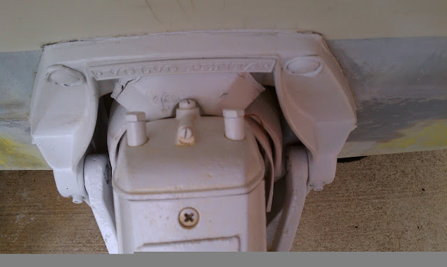
The black arrows show where the bearing seats;
(the other arrows were for another demonstration)


.
 

Attachments

  • 270 280 Intermediate housing.jpg
    270 280 Intermediate housing.jpg
    37.5 KB · Views: 332
Last edited:
Back
Top