Logo

87 yamaha outboard going into limp/safe mode

Hi!
I have a 1987 yamaha 90hp outboard jet motor that is going into limp mode after about 1-2 minutes of operation. When I bought the boat 4 years ago, the oil pump was bypassed already. When it goes into safe mode the motor is running fine it is just at reduced RPM. No missing or sputtering. I have a service manual, and as far as I can see the only two reasons for it to do this would be the Temp sensor switch and the oil sensor switch. I ran the test on the heat sensor and it appears to switch off and on within the temp limits. I recently changed the water pump impeller and it shows a strong steam of water exiting the motor. I ran tests on the oil sensor too but I am curious, can I disconnect all those wires since it is bypassed? at a loss... any help would be appreciated. Thanks in advance
 
Oh. That is not a safe mode. Nothing safe about continuing to run the motor with the alarm sounding. Keep at it and you will have a much bigger problem.
 
90 ETLH Is the model.
I am not keeping at it, just so you know. This is a recent problem that I’m trying to fix. This motor doesn’t have an alarm sounding it just reduces rpm.
 
I did another test as described in the service manuel on the thermo switch. I put the bottom of the switch in water and heated it up connected to my fluke multimeter. At first there was no continuity. Open switch until the water reached 187 degrees. The switch then had .3-.4 ohms on it. Then I let the water cool on its own. At 153 degrees the resistance jumped to 20-23 M ohms. It then continued to clime in M ohms to 42 and then it opened at a temp of 125 degrees.
(ON temperature a:
84 ~ 90˚C (183 ~ 194˚F)
OFF temperature b:
60 ~ 74˚C (140 ~ 165˚F) )
a little outside the range of what the book says.
Anyone think that this switch is the problem?
 
90 ETLH Is the model.
I am not keeping at it, just so you know. This is a recent problem that I’m trying to fix. This motor doesn’t have an alarm sounding it just reduces rpm.
That is another problem that needs to get fixed. Is the motor tiller steered or remote steered? Left the factory as a remote steered model. In which case there is a key switch panel that has a warning horn adjacent to it.
 
I did another test as described in the service manuel on the thermo switch. I put the bottom of the switch in water and heated it up connected to my fluke multimeter. At first there was no continuity. Open switch until the water reached 187 degrees. The switch then had .3-.4 ohms on it. Then I let the water cool on its own. At 153 degrees the resistance jumped to 20-23 M ohms. It then continued to clime in M ohms to 42 and then it opened at a temp of 125 degrees.
(ON temperature a:
84 ~ 90˚C (183 ~ 194˚F)
OFF temperature b:
60 ~ 74˚C (140 ~ 165˚F) )
a little outside the range of what the book says.
Anyone think that this switch is the problem?
Nope.
 
Once the warning horn is fixed, then as soon as you hear the horn (motor will also go into RPM reduction mode) quickly stop the motor and be prepared to inspect the thermoswitch to see if it is closed.
 
That is another problem that needs to get fixed. Is the motor tiller steered or remote steered? Left the factory as a remote steered model. In which case there is a key switch panel that has a warning horn adjacent to it.
It is operated remotely. I will look for a key switch panel and warning horn
 
Once the warning horn is fixed, then as soon as you hear the horn (motor will also go into RPM reduction mode) quickly stop the motor and be prepared to inspect the thermoswitch to see if it is closed.
just to be sure mr. Boscoe You do want me to perform this test on the thermo switch even though I did the bench test?
 
The remote control box. The one that is used to shift and throttle the motor. One style might have a key switch on it whereas the other one will have a separate key switch. That is where the warning horn resides.
 
The remote control box. The one that is used to shift and throttle the motor. One style might have a key switch on it whereas the other one will have a separate key switch. That is where the warning horn resides.
Okay,
so I haven't heard from in a while, so let me catch up. I have the oil tank (on the motor) drained and the oil sensor out. I checked it per the manual and I can see it going on and off with my meter. I put the oil sensor back in the circuit and with it in the low position I can hear the horn/buzzer go off up at the remote throttle with the key on. I had never heard it before. I put the boat in the water and started it up, and the buzzer went on. I positioned the oil switch for it to go off. Then I took off and the motor did fine until it shut down to a lower rpm (30sec?) and there was no buzzer. I pulled the top off and disconnected the temp sensor and hooked it up to the meter and it was open. No continuity. So now I'm back to square one.
 
I did some more research, and I am stumped. I was under the impression that to go into the low RPM mode it had to do with one of two things. Low oil or high temp.
 
I did some more research, and I am stumped. I was under the impression that to go into the low RPM mode it had to do with one of two things. Low oil or high temp.
That is normally the situation.

Keep in mind that the CDI box is looking for a ground to be completed to activate the warning horn. The ground normally comes from the oil tank sensor or the thermoswitch being closed. But a wiring fault can make the CDI box think that the ground is coming from a component.

This is what trouble shooting is all about. Understanding how a system is supposed to work and what can be happening if and when it appears to not be working.
 
The warning horn is grounded by a pink wire to make the alarm sound. If that pink wire were to get chafed to ground not only would the horn sound but the motor would go into RPM reduction mode.

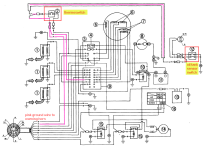
Can you make heads or tails out of wiring diagram?
 
That is normally the situation.

Keep in mind that the CDI box is looking for a ground to be completed to activate the warning horn. The ground normally comes from the oil tank sensor or the thermoswitch being closed. But a wiring fault can make the CDI box think that the ground is coming from a component.

This is what trouble shooting is all about. Understanding how a system is supposed to work and what can be happening if and when it appears to not be working.
I can appreciate that. I have been a high voltage lineman for 32 years and the last 10 years as a substation mechanic. I have learned all about elusive troubleshooting. I can read schematics and wiring diagrams. I have some auto experience and small motor experience as I do work on my stuff for the minor to slightly advanced stuff. I just have near zero in outboard motor stuff. I had someone to follow and collaborate with while gaining experience with the other stuff. On my own with this. And in this area there is literally hardly anyone who works on them. And if they do they are weeks and months out. Which leaves me. So, I appreciate your time and patience. I guess from what you said I should look at wiring to and from the CDI units? I think there are three if memory serves
 
The warning horn is grounded by a pink wire to make the alarm sound. If that pink wire were to get chafed to ground not only would the horn sound but the motor would go into RPM reduction mode.

Can you make heads or tails out of wiring diagram?
Haha. see above
 
No worries. I was writing it as you posted so you wouldn't have seen it. I never know how much background to provide either. I want people to know that I have some knowledge, but there is a reason I get help lol.
 
So I found two spots where the ground was bad between the thermos switch and the horn. But they are almost look like they are purposeful gaps. They have two connectors about an inch and a half apart, and our heat shrinked between them. Makes me wonder if they were put there on purpose but, after I removed those two spots, I have continuity between the horn and the thermo switch. With the switch on, I can still use the oil sensor switch to make the horn go on and off and if I hit the start on the switch, the motor tries to start so now I’m wondering if I had to try it on the water again?
 
What do you mean by the ground was bad? An open in the wiring or connectors that were disconnected? If connectors were disconnected I am guessing that some previous fool owner was trying to stop the warning horn from sounding as a stupid solution to a problem.

The start circuit is in no way connected to the warning circuits.

Since the motor is running on premix, and if it is known to be cold or not over heating, I would disconnect the pink wire at the CDI box. Then run the motor and see if it no longer goes into RPM reduction mode. Confirming that the CDI itself is not the problem.

If the motor now runs well with the pink wire to the CDI box disconnected, reattach the pink wire to the CDI box. Then disconnect the two pink wires that share a female bullet connector terminal. Top left on the diagram near the thermoswitch. Turn the key on. Does the horn sound? It should not. Run the motor again to see if the problem returns or if the motor now runs well. This will confirm that the problem is not in the wiring to the horn.
 
I can’t send pics on the app for some reason. Would you be willing to give me an email so I could send you a pic or two?

If not no big deal. The ground wire did not have continuity from the horn to the thermo switch. Thus the problem was the two spots I found “open”. One in the path between the thermo and the horn. One between another path in the ground path that branches from the thermo switch to the oil sensor ground.
 
Back
Top