Logo

270 (Actually Chrysler Marine) to SP swap

murfman

Regular Contributor
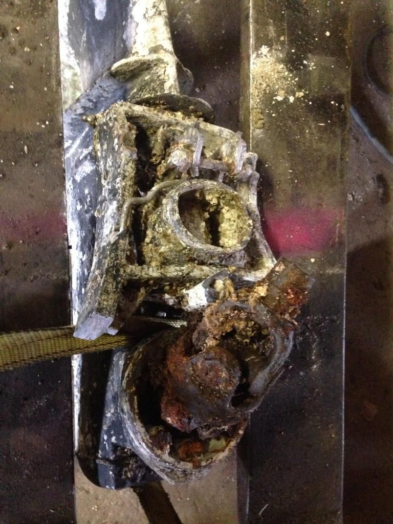
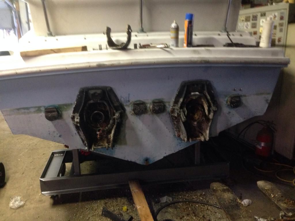
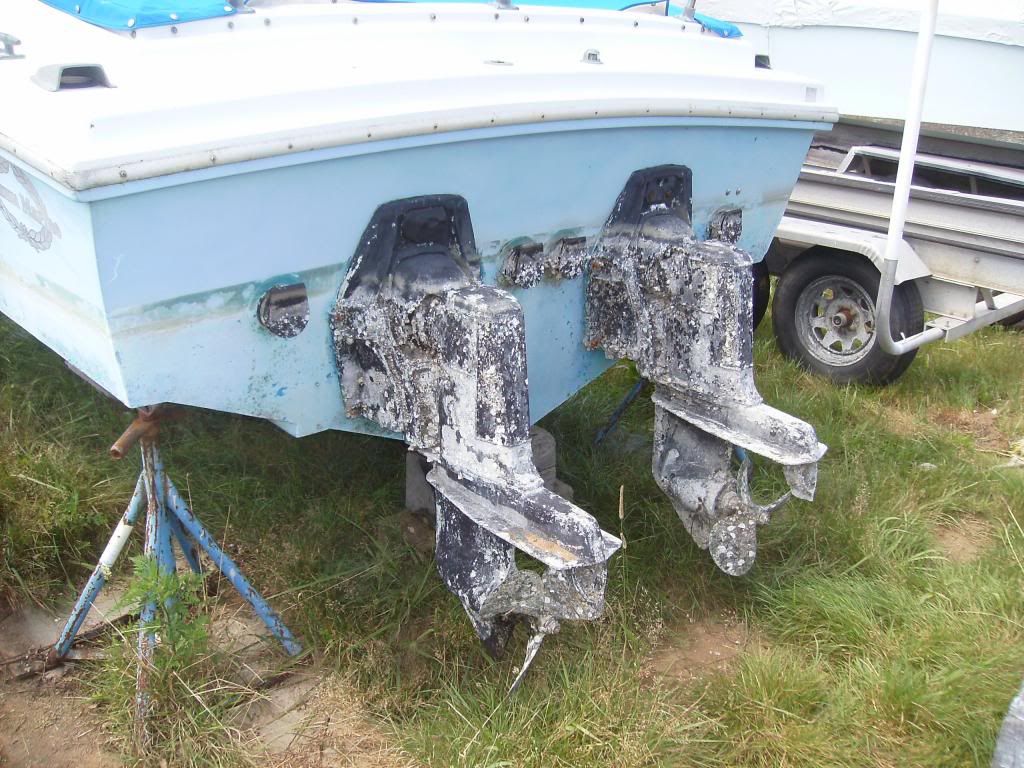
I recently bought a 1972 Magnum 27' Sedan that has the Chrysler/Volvo outdrives and 2 360 engines, I know they were originally 318 or 340 motors but that is not my concen. The boat is from CT and spent its life in saltwater, the drives were nasty, hose clamps and wire cables locking them down because the revers lock mechanisms were rusted solid, covered with Barnacles, the steering was frozen on both drives. I had to cut the suspension arms to get them off as the bolts for the pins were siezed and stripped, tried my best with PB-40 Aerokroil and heat, got 1 out of the 4 bolts out and finally said the heck with it, I want to replace them with freshwater units anyway.

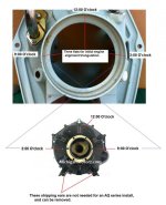
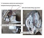
I have a few questions, I was able to get the Helmets off of the drive and steering forks, I also got the bolts out that hold the retaining ring to the bell housing. How do I get the retaining rings out?

I also want to upgrade to the 290 / SP CD Trim style transom assys to get power trim. I understand I will have to enlarge the cutout in the transom, and may have to move the engines forward a little?

Finally the 270 outdrives I have shift nice and turn smoothly so I'm thinking the internals are good. If I were to buy a V6 or 4Cyl SP drive woud the gearsets from the lower housing in my 270 work in the SP case? just a thought as I have found more 4 and 6 cyl SPs than 8 cyl ones locally, and it was just a thought. Either way I plan on tearing down whatever drives I get to make sure everything is n working order before I install them in the boat. Thanks Murf

Warning if you are squeamish dont look at these pics!


Well, I'm halfway there! I just bought a 1989 SP CD Trim outdrive/transom assy from a 5.7 Liter boat locally. Now to find a matching one. I am picking it up tomorrow, how can I tell if its a SP A, SPA1, or SPA2 drive?
 
Damn, them are some ugly fugly drives!!!! Lower unit are where the ratio changes in VP AQ's so the lowers are wrong ratio. The uppers may work but looking at those drives, I wouldn't want the stink in my shop.
 
The funny thing is they shift like butter and the prop shafts have no end play and turn super smooth. I took one top cap off and the bearing and internals from what I can see look to be perfect. If the internals are interchangeable between the 270 and 290, I'll tear them down and keep the internals for spares.
 
Here is the SP I'm picking up tomorrow

It is in slightly better shape...


How can I tell which version of the SP it is? Obviously it is not an E.
 
The flywheel cover clamping rings (that you want to remove) will be threaded for three 3/8" NC "jack" bolts. With all of the corrosion that I see, I doubt that these are going to be useful.
With the six Tap bolts removed, I would drill a series of holes across the clamping ring faces, then take a chisel and split the ring (just simply sacrifice them), and try to remove these in pieces.

Your original drives are 250s.
The OEM Chrysler-Volvo Penta PDSs will be course spline, whereas the later SP female yolks will be fine spline.
Depending on which bearing crosses the SP drive universal drive shafts are equipped with (internally clipped or externally clipped), the female yokes will need to be changed to course spline.

Your final drive reduction will need to be 1.61:1.

The one newer drive may be the A version SP.


.
 
Last edited:
Yes the PDS is coarse spline, I assume if the bearing crosses are the same type I can re-use my yokes. The drive I am picking up tomorrow came from a 350 powered boat so
i assume it will be a 1.61 ratio, I will check it before I purchase it. Thanks for the info. I will start drillin and chislin tomorrow evening. I'm thinking the port side ring may come out with the jack bolts, that engine had been replaced somewhat recently and the tap bolts were clean stainless bolts that came out very easily. The starboard bolts were carbon steel, but suprisingly came out pretty easily as well. I'll keep my fingers crossed.

Once the claming rings are out the flywheel cover should slide out of the transom, correct? The flywheel covers are really the only parts I am trying to save at this point.

Anything else I should look at on the SP drive tomorrow before I buy it?
 
In the 23 or 24 years that I've been servicing the AQ series drives, I've seen only one or two of the later style "externally clipped" female yokes in course spline.

You'll easily find the other style in course spline.

.
 
I took a closer look at the SP drive and transom shield.

Suggestions:

I would remove the hydraulic cylinder hinge pins while this area is still easily accessible. I'd then clean things up... grease well... and re-assemble.
The pins are hydraulically pushed out with grease gun pressure. Heat in this area will also help.

I'd take a good look at the shift cable sheathe where the crimp sleeve is. These sleeves rust out occasionally, and if/when they do, the rubber hose may begin to leak at the fitting.
DO NOT attempt to remove the actual fitting from the shield. Trust me on this one!
The fix: chisel the sleeve away.... pull the sheathe from fitting..... cut about 1" off the sheathe.... re-install with a Euro style SS clamp of the correct diameter for the rubber hose.
 

Attachments

  • SP A shield and drive.jpg
    SP A shield and drive.jpg
    81.4 KB · Views: 110
BTW..... whether you have the 1 pc flywheel covers, or the Borg Warner - slash - Volvo Penta PDS adapter housings........ you'll want to replace the PDS bearings.


This is the Volvo Penta/Borg Warner PDS adapter unit that mates to a Borg Warner pattern flywheel cover.

$T2eC16VHJHQFFhc)ppPBBSD6OK450w~~60_35.JPG


Here's a GM Volvo Penta AQ series 1 pc flywheel cover... similar to what the Chrysler would look like.

1_a67f531f-299f-414b-93cc-ea5d17d9bf36_medium.jpeg


I'd strongly encourage you to replace these PDS bearings.
 
Thanks for the input. One more question, once I remove the retaining ring can I remove the engine while still attached to the FC?
 
Thanks for the input. One more question, once I remove the retaining ring can I remove the engine while still attached to the FC?

Let me see if I'm understanding your question.

Transmission and/or drive removed.
Remove the six clamping ring bolts.
Remove the clamping ring.
Slide the engine FWD and out with the Flywheel Cover still attached to the engine.

Is this correct?

If so.... yes!
Once out, you can remove the F/C's for the PDS work.

However, when going back together, you'll want to know that the inside rubber cushion provides the water seal.
Both together, these provide the rear engine support and isolation... IWO, the rear engine mount.

At minimum, replace the inside rubber ring cushions.


BTW, these six bolts are 3/8" NC "galvanized" carbon steel "tap" bolts (threaded up the entire shank).
A good bolt/fastener company can supply these for you at a fraction of what V/P wants for them. It may take a day or two to bring them in for you.


.
 
Last edited:
Yes that is what I meant. I was hoping I could pull the engines like that because with twin V8s in a hull that has less than an 8' beam there is not a lot of room. I removed the exhaust manifolds to give me some room and could barely get the manifold off the studs as it was hitting the manifold on the other engine. I actually had to use a pry bar for the last 1/8". While looking at the motors I noticed the port motor is not square in the boat so that made it worse as it is closer at the front than the rear by 3/4". Obviously when it was replaced someone did not line it up correctly. I will fix that upon reassembly.
 
While looking at the motors I noticed the port motor is not square in the boat so that made it worse as it is closer at the front than the rear by 3/4". Obviously when it was replaced someone did not line it up correctly. I will fix that upon reassembly.
Since the Port Engines was not aligned correctly, you may want to infill the previous engine mount lag screw holes in the stringers.

There is an initial one-time-alignment-triangulation procedure that you'll be following when you re-install these engines.
The goal will be equal distance between each pair of "flats".
With the new rubber cushions in place, and with the clamping ring not yet fully tightened (snugged up... but not yet tight)...... you'll be raising/lowering the engine mounts and shifting the engine Port/Stbd as you watch the flats.
Once equal, the clamping ring will be fully tightened up.
Only now will the lag bolts will be installed.

Good idea to spray silicone on the rubber rings while doing this.
 

Attachments

  • Initial engine alignment triangulation 2.jpg
    Initial engine alignment triangulation 2.jpg
    60.5 KB · Views: 109
Last edited:
Thanks again for the input. I can see the mounts actually look twisted so I'll refill and mount everything from scratch. I think I eras somewhere that the 290/SP transom bracket is deeper into the hull
and moves the engine a little forward compared to the 280 and down models, is this correct?
 
Another question, are the lower gears and shafts interchangeable from my current 250 housings to a 290/SP lower case? I found another SP complete from bell housing to prop, but its a 2.12 ratio, if I could replace the lower gears with the ones I currently have I'll be all set.
 
............ I think I eras somewhere that the 290/SP transom bracket is deeper into the hull
and moves the engine a little forward compared to the 280 and down models, is this correct?
It will appear to be deeper due to the base hydraulic cylinder mounting.

1..... Another question, are the lower gears and shafts interchangeable from my current 250 housings to a 290/SP lower case?
2.... I found another SP complete from bell housing to prop, but its a 2.12 ratio,
3.... if I could replace the lower gears with the ones I currently have I'll be all set.
1.... Short answer... NO!
The 250 lower unit gears are bevel cut gears, whereas anything past the 250 are hypoid cut gears.
Housing, prop shaft and the bearing carrier are all different.


2.... This part is actually a flywheel cover (bell housing in the automotive world)....... and this no 2.12:1 ratio.

Single Prop AQ series ratios are as follows:
2.15:1 = 4 cylinder engines
1.89:1 = in line 6 cylinder engines, and some V-6 engines.
1.61:1 = all V-8 engines.... small block and big block.

Duo Prop AQ series ratios are as follows:
2.30:1 = 4 cylinder engines.
1.95:1 = small block V-8 engines.
1.78:1 = big block V-8 engines.


3.... the 280 1.61:1 lower unit would work (when shimmed correctly), but is lacking the exhaust outlet flapper.

A 290 flapper can be retro fit to the 280 housing.... and the two drives would appear to be the same, and would both function identically.


.
 
I picked up the SP-A drive with the transom plate, he even threw in the Flywheel Cover/PDS for a small block Chevy and an exhaust Y. The drive is very clean, but I am thinking about completely disassembling the unit and getting everything Powder coated. Am I asking for trouble? Are there any specialty tools needed for dsiassembling and assembling the gear train in the lower unit or transmission? Or removing the housing from the fork? I want to make everything "right" on this boat the first time. I have a local Powder Coating shop that does phenomenal work so I know the drive/transom etc.. would look better than new when finished. This way I figure I can check all the internals and re seal the drive while I'm at it. Is there anything else I should look for on the drive before or during tear down? Other than O rings and gaskets for the drive, the big donut seal, the bearing cross bellows and the water pick up hose are there any other parts that need to be replaced? I've seen rebuild kits for the trim cylinders on Ebay, is there a better source for these parts? I ordered a Manual for the drive but it is not here yet.
 
Yes there are special tools to make the job easier but I would wait for your manual and then go through it to see if you want to tackle the job.
 
.......................
I picked up the SP-A drive with the transom plate, he even threw in the Flywheel Cover/PDS for a small block Chevy and an exhaust Y. The drive is very clean, but I am thinking about completely disassembling the unit and getting everything Powder coated. Am I asking for trouble?
I'm not sure about the powder coating idea. I'd prep the aluminum, but I'd leave as much as posible of the OEM paint, and do a color matched epoxy paint over a very light coating of zinc chromate on any bare aluminum. Bring the parts up above dew point temperature prior to applying.

Are there any specialty tools needed for dsiassembling and assembling the gear train in the lower unit or transmission? Or removing the housing from the fork?
Yes and No! More so will be experience.

This way I figure I can check all the internals and re seal the drive while I'm at it.
A re-seal would be imperative, IMO.

Is there anything else I should look for on the drive before or during tear down? Other than O rings and gaskets for the drive, the big donut seal, the bearing cross bellows and the water pick up hose are there any other parts that need to be replaced?
Yes.... when you remove the transmission, look at the brass split ring keeper (at the bottom area of the vertical shaft) for any signs of expansion.

NOTES:
  • the new eccentric piston seal is directional (easy to miss if not aware).
  • both single prop drive prop-shaft seals face back-to-back..... and w/ lip and tension springs apposing one another.
  • when changing a transmission or a lower unit from one Intermediate housing to another, critical shimming is required.
  • after replacing PDS bearings/seals, pre-fill the grease cavity while rotating the PDS. Use high pressure bearing grease... not green marine grease.
  • install seals only after grease is visible through the ball cages.
  • Both 35x62x7mm PDS seals install with the lip and tension spring aiming AFT (there's a reason for this).
  • Glue or stake the FWD seal in place as to avoid future grease gun pressure from dislodging this seal.


I've seen rebuild kits for the trim cylinders on Ebay, is there a better source for these parts?
No OEM parts that I know of. Bill Lawrence sells these in kit form.

I ordered a Manual for the drive but it is not here yet.
Purchase the Volvo Penta OEM work shop manual if you can......... not the Seloc or the Clymers!


.
 
Last edited:
Any sources (Ie Junk yards) that still have Volvo AQ drives lying around? I'm not in a terrible rush, but still need a matching second for my drive. Most of the ones I find are 4 cyl models. Also, anyone have a PDF of the cutout template for the 290/SP drive? I'd like to print one life size to set up my hull. If all goes well, tomorrow I will pull the engines and the transom plates, I can then get a nice look at the transom to see how much work I have ahead of me lol.
 
I have a 280 lower in the 1.61:1 ratio. Lots of hours on it while running a left-hand propeller. It would be a good candidate for your Starbord drive running a right-hand propeller.
Any of the 290 or SP transmissions and intermediate housings will work with this.

Shoot me a PM with your email address if you're interested.


.

Did you get my PM?
 
Back
Top