Hello Everyone,
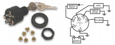
I'm wondering if anyone can help me with wiring in a new ignition switch. I have a 1958 Evinrude Lark 35hp with a 3 position 4 terminal ignition switch and I went to the boat store today excited that I might be able to finally get this motor started today. I bought a 6 terminal 3 position starter from them because they told me it would work I just wouldn't have to use all of the terminals. When I got home and took it out of the package I realized that I didn't know which terminals needed to be used. the new ignition switch is a sierra MP39760 and has a wiring diagram shown below.

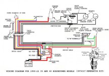
Now the real question. The old ignition switch has the two M terminals and a wire attached to each one leading to the upper cylinder armature plate assembly and the other leading to the cutout swtich and then on to the lower armature plate assembly. The new ignition switch has one of the M terminals going to ground and the other going to the magneto system. Can I connect both of the M terminal wires to the outgoing M terminal on the new ignition and the connect the seccond M terminal to ground? Also, On the new ignition switch will I need to connect anything to the I terminal, ignition circuit?
Thank you
I'm wondering if anyone can help me with wiring in a new ignition switch. I have a 1958 Evinrude Lark 35hp with a 3 position 4 terminal ignition switch and I went to the boat store today excited that I might be able to finally get this motor started today. I bought a 6 terminal 3 position starter from them because they told me it would work I just wouldn't have to use all of the terminals. When I got home and took it out of the package I realized that I didn't know which terminals needed to be used. the new ignition switch is a sierra MP39760 and has a wiring diagram shown below.
Now the real question. The old ignition switch has the two M terminals and a wire attached to each one leading to the upper cylinder armature plate assembly and the other leading to the cutout swtich and then on to the lower armature plate assembly. The new ignition switch has one of the M terminals going to ground and the other going to the magneto system. Can I connect both of the M terminal wires to the outgoing M terminal on the new ignition and the connect the seccond M terminal to ground? Also, On the new ignition switch will I need to connect anything to the I terminal, ignition circuit?
Thank you