PatinIdaho
Regular Contributor
Seems like there is just no way to really know though.
MarineEngine.com does not offer troubleshooting assistance or repair advice by email or by telephone.
You are invited to join our public Boat Repair Forum to seek assistance from other members.
You may also visit the Boat Motor Manuals section of our site to obtain a service manual.
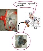
 . Going to check it later today and if still holding then tomorrow morning i spect it will still be holding
Ok Shift gears a little bit for a few minutes.
That will rotate the eccentric piston.... good call.
You'll also want to rotate the prop shaft while under press/vac during the LD test.
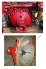
Went and did a dumb thing.
I have new gauges coming so i took out the old gauges. Wiring was kind of a mess so i took it all out figuring i could just look in the manual and fallow the diagram. Well there is none in the manual for wiring the instruments and switches.
I have been looking for one online but can't seem to find one that matches. I can find some that are close but missing the orange wire usually I have a 8pin plug with 8 wires. The awg is a guess
red (10awg) Helm power
black (10awg) Helm Negative (technically there is no ground in 12vdc system)
orange (10awg) This is typically seen when an Amp Meter is at one helm or the other.
This would mean power To/From the Amp Meter and back to the engine/hull harness..... I.E., a potential voltage loss.
I would eleminate an Amp Meter in lieu of a Volt Meter, then abandon the orange circuit.
gray or white (14awg) usually tachometer
purple (14awg) ignition
tan or brown (14awg) temp gauge
lt blue (14awg) oil pressure
Im sure a multimeter and a day could fix it also but a diagram would sure be nice if some one has one.
3RD gear:rolleyes:
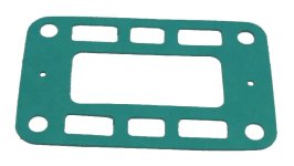
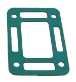
I read some place (i though in this thread) that when replacing the exhaust elbow gaskets you want to use the fully open ones.
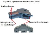
The AQ series exhaust system does not accommodate a Full Closed Cooling system.
(manifold supply ports are too small, elbows are not ported, and the down angle of the elbow does not allow for a ported riser/spacer)
If you are either seawater or closed system cooled, the exhaust Elbow transfer ports must be fully open.
Well i ordered the ones like the ones that came off when i took them off with little holes on the ends not fully open style. I can change that though if the fully open ones are the proper gaskets to use by just cutting out the ends?
See above.
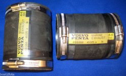
Also Ricardo you mentioned to order the flexible exhaust hose 2 inches longer then what i have.
These use 95mm soft wall Marine exhaust hose, of which is not actually flexible in terms of making angle turns.
This 95mm soft wall hose can be somewhat difficult to source.
Mine measure 6in so i need 2, 8in sections?
The OEM are almost always too short. Why.... I don't know!
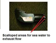
You'll need enough length so that the two elbow band clamps do not squeeze down over the scalloped areas of the elbow, and yet enough length to slip onto the Y-pipe with enough material for those two band clamps to tighten down on the pipe.
Reason: if the one of the two elbow clamps tighten down over the elbow's scalloped area, the hose will eventually become depressed into the scallops.
This will restrict outgoing spent seawater and may cause over-heating.
Sorry for jumping all over the place but im getting to the little bits finally.
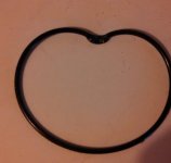
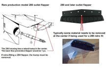
My exhaust flapper arrived today and im wondering if anyone has some measurements on drilling the holes for mounting it on a 280 drive. Or a few pics so i can at least try to match the bend radius.
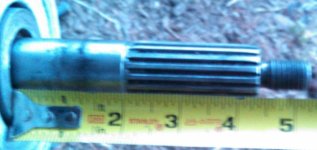
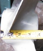
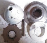
So i need a new prop and i think what i have works but is not the right setup
I Think i have a long shaft with a short hub?
I have looked at some pics but they all show to measure from a shoulder to the end of the splines or end of the threads
So im a little confused
Sorry there not clearer. Can't find the good camera!
Also any help with above post #107?
I have a fitting made up with a pressure gauge attached so now i can do a proper p/v test.
The test procedure ill use is on page 126 of the manual i have. Its does not list time for total test.
It does not say how long to leave it or how much p/v to use after the initial high pressure and vacuum test.