Logo

98 Johnson 25hp J25TEECB Starter Solenoid Wiring Diagram

Sunshine1

New member
Can anyone point me in the direction of a wiring diagram for starter and starter solenoid for the above mentioned motor (J25teecb)? I've googled and searched to no avail. Or snap a picture of theirs, or help in any way, shape, or form?

My buddy replaced his starter and did not label his wires or anything and can't remember how they go back together, so now it's sitting in my back yard because, being the nice guy I am, I always offer up my assistance before I can think to cram my foot in my mouth.
 
Well, no diagram is really needed. I don't have one, but I can describe the wiring., if you wish.

Solenoid has 4 terminals. Two very large terminals are for the battery cable and starter, two smaller terminals are for the control circuit and ground.

So: Locate the two very large terminals; they are opposite each other on the solenoid.

1. Connect the large wire FROM the starter to one of those large solenoid terminals. It doesn't matter which one, but you might be able to tell where it went originally by the length, bends, etc. No other wires on this terminal.

2. Connect the small black wire(s) to one of the two smaller terminals.

3. Connect the yellow/red wire to the OTHER small terminal. No other wires on that terminal.

4. Connect the positive battery cable to the large terminal opposite of where the starter wire was connected at #1 above.

5. There will be at least one or two other wires...a red/purple for sure....connect the red/purple to the same large terminal that the positive battery cable is attached to.

If there are other strays, post the color and I will tell you where it may go.
That should be all of them, tho.
 
I wish! I haven't had time to mess with it until today.

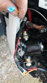
Here's what I have, the red and red/yellow wire coming from the top of the picture goes to the push button start. The yellow/red wire in my hand leads to the bundle of wires going forward to the center console. The red and red/yellow wires coming from bottom go up and over the motor to a terminal block on the other side. I see no black/ground wires hanging out.
 

Attachments

  • solenoid.jpg
    solenoid.jpg
    29.4 KB · Views: 8,756
no idea why pics are so small, can get better ones if you can't make it out.

try this again, #1 is red/yellow wire coming from push to start #2 is red/yellow wire coming from the wire bundle going forward to the center console #3 is a red/yellow wire coming from the opposite side of the motor on a terminal block, #4 is bundled with #1 going to the push to start, #5 is with #3
 

Attachments

  • holycowwhyisthissohard.jpg
    holycowwhyisthissohard.jpg
    57.6 KB · Views: 1,085
Last edited:
At post #3 above, Kim posted a link to a very good diagram. It is not your year model, but it is the same.

Look at his diagram, and compare my description to the diagram. Get an understanding of the circuit.
In my description, I left out one wire. There will also be a large red wire coming from the reg/rectifier that
attaches to the same large solenoid lug that the battery cable attaches to. You will see that one as you study the diagram.

You will see there absolutely has to be a ground going to one of the small lugs of the solenoid.

Your pics....too small.
 
I have no idea how to correctly post a picture on this forum, short of hosting it on another site which I can try to do when I get home from work. If you right click on the image and select "Open in new tab" it may bring it up a bit bigger.

I did view the diagram, it has a 4 wire push to start that goes to a terminal block, this is a 2 wire push to start and it goes to the solenoid. There is only one yellow/red wire on the diagram. I have 3 yellow/red wires to work with. Running a ground is not a problem, I just don't know where the last one went.

The large red wire coming from the reg/rectifier that you mention and I attached to batt +, it is bundled with a red/yellow wire coming from the same place with a small ring terminal. I assume it goes to the small post, opposite of the ground. Then the red/yellow wire coming from the console goes to that same small post based on the diagram. Then I must ground one of the small posts. This sound correct?

If so, that just leaves the wiring of the push to start. Since this is already set up for remote start, and he said the push to start worked intermittently before, I'm sure he could do without it, but if we can figure it out, even better.

I do really appreciate your help. Thank you.
 
Is the solenoid mounted on the starter bracket ?-And is the solenoid a factory unit or an aftermarket that looks the same ?
 
I need to understand why you have so many yellow / red wires involved. That doesn't make sense so I have sent you a private message if you would call we can discuss it.
 
Can't really tell, but that sort of looks like a car solenoid. If it is, get rid of it and buy the right kind. There is​ a difference.
 
Back
Top