Logo

Torque setting vaves and rockers 1990 454 crusader model 350

contender31

Regular Contributor
Hello I want to clarify the accurate torque setting for my 1990 454 model 350 454 Crusader. My mechanic claims 50lbs ??? Anybody have a any knowledge of the correct settings? Installing reconditioned heads

Thanks in advance
 
Your thread title reads: Torque setting vaves and rockers 1990 454 crusader model 350

I assume that "vaves" should read "valves", correct?

Assuming that this is correct, and that your cam followers are hydraulic, we're not actually setting valves or adjusting valves per 'se.
We're setting the plunger depth within the cam followers.
(more on that later if interested)

Why your mechanic is suggesting a XXlb value, I'm not sure.

Can you get back to us and clarify?


.
 
Last edited:
There's diferent designs out there. One is done by adjusting the rockers to take the slop out, then add a turn or so. Newer systems just bolt the rocker down. You need to determine which you have.

Jeff
 
Rocker studs torque at 50 ft lbs, is that what he was refering to? Heads themselves torque at 75-80 ft lb for the long bolts and 65 to 70 ft lbs for the short bolts. I don't know of any torque setting on the valves.
 
According to MichiganMotors.com, the 1990 and earlier 7.4L uses rocker arm studs.

If this is correct, I believe that you will be adjusting the cam follower plunger depth once past ZERO rocker arm/valve stem lash.
This will be stud thread pitch X's nut adjustment (past zero) X's rocker arm ratio. This will give you the correct plunger depth.
See your OEM specs for how many turns past ZERO lash.

Your first post says that you are installing reconditioned cylinder heads. Basically, you will be setting these as though this is fresh engine.
A caution and FYI for you if I may:

You'll find that many will suggest the 2 stop method. Why..... I don't know! :mad:
I would NOT recommend using the 2 stop procedure. IMO, it gets you close only.
We want the cam followers to be at the center of cam lobe Base Circle during this adjustment.

Instead, use the 8 stop procedure.
The 8 stop is very similar to the 2 stop, except that you'll be stopping at each cylinder's TDC C/S! (8 x's -vs- 2 x's)
You'll go right on down the firing order (beginning w/ #1 TDC C/S) adjusting both Intake and Exhaust.
Rotate crankshaft 90*, and you're ready for the #8 cylinder (Standard LH rotation engine).
Rotate crankshaft 90* again, and you're ready for the #4 cylinder.

Takes a bit longer, but you'll end up with a more accurate initial setting.

If you'll use the 8 stop procedure, I doubt that you'll need to go back through these dynamically later on.

Your call.... I'm just offering you a heads-up if you weren't aware! :D

.
 
Last edited:
Here's the original question.

Hello I want to clarify the accurate torque setting for my 1990 454 model 350 454 Crusader. My mechanic claims 50lbs ??? Anybody have a any knowledge of the correct settings? Installing reconditioned heads

The original question leaves a bit to the imagination. The rocker STUDS go to 50ft-lbs. But, not the rocker nuts.
Dave, I agree with you. Much of that is rather vague.

He uses the term "correct settings" and then says; "Installing reconditioned heads"

In my way of thinking, "reconditioned" cylinders heads would have come back from a machine shop with the rocker arm studs having already been installed correctly.
That's why I offered the cam follower adjustment info.

Guess we'll have to wait and see! :D


.
 
I also have used RIck's rotate the crank a bunch and do it right method, and for half a century! That BS saying you can adjust all the valves in a V-8 by putting it in only two rotations is nuts! Why? 'Cause it's extremely easy to mistake a, say, 4E for a 4I rocker, and that can be disatrous! Especially if you're working in semi-darkness between rounds thrash at a drag strip!

To wit: The intake and exhaust on ONE cylinder can NOT be all the way up at the same time. So, if you open an intake ALL the way, you can adjust the exhaust for that hole and know it will be fully closed. Then spin the crank over 'til the exhaust for that hole is all the way open and adjust the intake. Then go to the next cylinder and repeat. Unless you've put away a six pack earlier that day, you can't screw it up.

Jeff
 
First, let me back here.
I'm assuming that "contender31" is wanting a rocker arm/cam follower adjustment procedure since it's rather unclear in post #1.

But I agree:
I also have used RIck's rotate the crank a bunch and do it right method, and for half a century! That BS saying you can adjust all the valves in a V-8 by putting it in only two rotations is nuts! Why? 'Cause it's extremely easy to mistake a, say, 4E for a 4I rocker, and that can be disatrous!
Not just that alone!
With the 8 stop procedure @ TDC C/S, we pretty much ensure that the cam follower is at the base circle low point.
The difference is only 6 more stops..... and is hardly anything to sweat over. :rolleyes:


Jeff, good to hear that you're on board with this.
This silly 2 and 3 stop procedure can be found in OEM manuals, if you can believe that! :mad: Sheesh!

I've argued and debated this many times over the years. In some 47/48 years, I have NEVER used anything but the 8 stop procedure. I can almost guarentee that anyone using the 2 or 3 stop, will be going back through these dynamically.
Nothing wrong with doing these dynamitcally, but when the 8 stop is used correctly, we'll seldom find ourselves going back through them.

I'll go one further if you'll bear with me:
When assembling a fresh engine, I do this procedure prior to the intake manifold being installed, and prior to priming the oil system.
With the cam followers not yet having oil in them, the plunger is free to move within the cam follower body.
This allows us to view the push-rod cup (aka socket) as it as we reach ZERO lash.
If we look closely, we can see when the plunger just begins to move away from the cup retainer clip.
I've always viewed this method as being more accurate.
But each to his own! :D


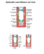
Here's a neat little GIF file that shows a cam follower just prior to oil pressure, and then after oil pressure.
Note that the plunger is free to travel fully prior to oil and/or oil pressure.
(on average, plunger travel is approximately .100" +/- ..... our goal is setting the plunger depth as per the OEM engineers)
Once oil pressure is realized, the plunger is now subject to the cushion of oil.
 

Attachments

  • Cam follower cut view.jpg
    Cam follower cut view.jpg
    36.9 KB · Views: 199
Last edited:
Like your manifold off valve adjustment technique, but I couldn't do that with the last V-8 I built: it was a Caddy 4.9 liter: the push rods go through the intake manifold!

Jeff
 
Back
Top