Logo

Question about charging system....

firepiper

Contributing Member
Trying to separate battery banks. I'm going to have one engine charge the house bank, though, it is started by the engine bank. The alternator has a yellow (exciter) wire, and an orange (charging) wire. I think all I have to do is send the orange wire from the alternator to the battery. Is that correct? Thanks.
 
I'd consider leaving the alternators as they are for now. Just make sure that each has a good independant Negative to Engine block, and that the charge leads are sized appropriately.

Is the boat now set up with an MBSS.... (main battery selector switch)? Or a pair of MBSS's?

Typically, until we get up into larger boats, our Stbd engine alternator, and 2nd Battery Bank, will serve as the House Load Battery Bank and charging system.
If you wish to bring in the Port engine alternator, consider a Bluesea ACR or a VSR to do the engine alternator combining automatically for you.
This way you will not need to separate your system out, and yet it will maintain your redundancy re; ability to combine, should you need to.

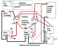
Bellow is a very basic, yet very dependable twin engine battery scenario that uses two MBSS's.
This still requires manual battery management, but for many of us, this is not an issue!
This also gives you the option of a Stbd side cranking battery (not shown) if you want to.
( I crank my Stbd engine on a large House Load Battery Bank.... no issues to date)
Note the option for a helm switch activated "Solenoid Combining Switch" (for engine cranking..... not alternator charging).

IMO, combining should be reserved for emergency use..... not necessarily charging unlike battery banks.
You can add an ACR/VSR to this.

attachment.php


This is simply a suggestion, as there are many ways to skin the cat.... some better than others.

.

.
 

Attachments

  • Twin Engine Battery schematic for Tom option 2.jpg
    Twin Engine Battery schematic for Tom option 2.jpg
    35.2 KB · Views: 39,834
Last edited:
Basically, that is what i have now. Star engine/batt is also house, (8d). Port engine/batt is for port engine, (4d). I'd like to make it so the 8d is powering house loads, and being charged by the starboard engine/alternator. Then the port batt would be dedicated for starting BOTH engines, and would charge from the port eng/alt. I have twin mbss on a blue sea panel, and would still be able to combine via mbss in emergency.
This setup would minimize voltage drops in the house system when starting one or both engines, (radar, t.v. , computer etc).
I think this would work, running the charging lead off star alt, and running to star batt. But, what about the yellow exciter wire? Thanks, Mark
 
Mark, I don't believe that you need to do anything with the alternator excite circuit.
As long as the Alternator charge is being directed to a Battery Bank, that Battery Bank voltage will predicate the charge rate.
BTW, All Negatives will need to become "common" if not already. (IOW, both engines will need a joining Neg cable connecting the two)
Engine Blocks are our Negative Common connecting point..... or should be! Especially if you have or install a LINK system.

One of the advantages of using the starter motor "common" cable for both Positive engine cranking supply...., and outgoing alternator charge, is that either is drawn from OR charged to the battery bank that is currently being selected.
If you wish to completely take the House Load Battery Bank away from the Stbd engine, then you have some wiring changes to make.
I'd then use an ACR/VSR to bring your Port engine alternator (actually, both engine alternators) into the charge loop for the now independant Stbd side House Load battery bank.


As for loads during cranking.... (if you left the system as-is)....., I'd suggest the momentary combining solenoid, or something similar.
I doubt that loads shared by the Port Cranking Bank, would affect the HLBB all that much.
But I understand your reasoning!

Like said, my Stdb engine cranks on my larger Stdb side HLBB.
These engines pop off quickly, and to date, no issues what-so-ever.
I also have my LINK system monitoring the HLBB only. No issues there either.

As per the schematic that I posted, the only item that my system does not use, would be the #2 to #2 inter-connecting cable for manual combining.
When/if I should need to combine, I use the momentary helm switch to activate the solenoid switch (as shown in the schematic).
I believe that the heavy duty version of the ACR or VSR can also do this.

What I also do NOT have, would the capability for Port Engine Alternator charging for the House Load Battery Bank.
(I have a CZ4 (4kw) Kohler on board)
However, an ACR is for this is on my To-Do list.
And again, it won't affect my LINK system due to the correct Negative connections.

.
 
Last edited:
Trying to separate battery banks. I'm going to have one engine charge the house bank, though, it is started by the engine bank. The alternator has a yellow (exciter) wire, and an orange (charging) wire. I think all I have to do is send the orange wire from the alternator to the battery. Is that correct? Thanks.
Hmmm. Now I wonder about that yellow wire, as yellow is GROUND on boats.

Anyway, I have a single engine, and two battery banks. I have my charge system set up with both smart alternator regulator (Balmar ARS 5) and automatic battery charging of both banks with a Voltage Sensing Relay (yandina 150). I monitor both banks with voltmeters and ammeters.
If you are looking for an automatic solution that does away with the BSS (1,2,BOTH,OFF switch) and still offers emergency parallel capabilities, I highly recommend you visit balmar.net and start boning up on 12v power management tech.
In most all instances, the output of the alternators should be directed to the house bank with the start bank getting its charge from the house bank thru a VSR. Their Centerfielder enables both alternators to charge the house bank. Then a Digital Duo Charge is used to feed charge current to the start bank.
You should also look at BEPmarine.com and their manual battery management Clusters.
I think in the end you'll find that you really want a start battery for each engine with emergency switching between all three banks. The BEP Marine cluster is a simple elegant solution for this with minimum fuss.

Another great source of info on power management is Ample Power
 
Last edited:
  1. Hmmm. Now I wonder about that yellow wire, as yellow is GROUND on boats.
  2. In most all instances, the output of the alternators should be directed to the house bank with the start bank getting its charge from the house bank thru a VSR.
  3. I think in the end you'll find that you really want a start battery for each engine with emergency switching between all three banks. The BEP Marine cluster is a simple elegant solution for this with minimum fuss.


  1. On the later boats, yes.... but he's calling it an alternator excite circuit. Agree.... odd that it's yellow, unless a PO added this using an incorrect color!
  2. Fully agree.... that, or an ACR from Blueseas.
  3. Or....., and just a suggestion....., an automatic combining system that activates during Stbd Engine Cranking only. This saves the weight and occupies one less space that may otherwise be used for an additional House Load battery(s). Food for thought only.
There are so many ways to skin this cat. Some better than others, however.
 
Hi again, i'm calling the yellow exciter wire that....because the factory wiring diagram shows it that way.....what color should it be? Thanks
 
Back
Top