Hi all,
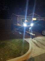
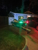
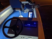
New to this forum and to boating in general. Last year I picked up a 15' 1975 MonArk with a 1961 Evinrude Lark III 40hp, model 35524. I've re-wired the boat (minus engine wiring), replaced the steering cable, rebuilt the lower unit, had it tuned it up, etc. It seems to be running well although I've only had it out on the water once so far (steering cable broke after about 15 minutes). I've attached some pics of this fun little project.
I have a problem that has me stumped. The motor won't turn off via the key so I have to throttle it all the way down to kill it. Replacing the ignition switch didn't solve it so now I'm tracing wiring and checking for continuity, etc., but I've reached a point where I don't know what to look for.
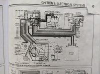
If I understand correctly (big if!), there are two wires connected between the ignition and the magneto, one of which is grounded to the powerhead. In the "off" position, this circuit is closed, grounding the line so that no spark is delivered to the plugs. I have verified that one of these lines is grounded to the powerhead and the other is not. I've also confirmed that the ignition switch is opening/closing the circuit properly. I am a bit confused by the wiring diagram in the service manual (attached). It shows two lines, each connected between the ignition switch and one set of points, but I don't see that either of these are grounded to the powerhead in the diagram. It seems maybe this wiring diagram isn't telling the whole story (e.g. where are the plugs and plug wiring?).
Obviously I'm missing something here. I need a better understanding of what I'm looking for and where to find it. Any help is greatly appreciated!



