Logo

Installing Pulse Pack on a 1969, Wire color prroblem

IGota69

New member
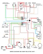
I am replacing the pulse pack on a 69 115hp. On here, the marineengine website, it said that the 385034 was the same as 113-8362 and so I ordered one from here. On the engine I need to connect to a blue and purple wire. This pulse pack has a green and red wire.

Also, the longer wires going to the sensor, I need a black and a white, but both wires coming from the pack are blue, so I don't know which one to connect to black.

Does anyone here know how to connect the colors correctly, as to not fry it?
 
Sorry, that wasn't real clear what I purchased. I got the 385034 Pulse Pack from MarineEngine.com. There was no picture of it, so I didn't know there would be the different color of wires.
Thanks for your replies
 
Sorry, that wasn't real clear what I purchased. I got the 385034 Pulse Pack from MarineEngine.com. There was no picture of it, so I didn't know there would be the different color of wires.
Thanks for your replies

Are you sure about that number. I see 765987.
 
Yes that is the number. Put that in the parts search and it pulls up this:

[h=1]0385034 - Pulse & Rotor Assembly[/h]
noimage.jpg


List Price

Your Price
$69.00

Part Number
0385034 Johnson
0385034 Evinrude
385034 Johnson
385034 Evinrude

Manufacturer
Evinrude Johnson OMC
VINTAGE

10+ In Stock.

SECURE CHECKOUT
SPEEDY DELIVERY
30-DAY RETURN
FULL WARRANTY


Evinrude Johnson OMC Pulse & Rotor A 0385034 is equivalent to parts:

  • 113-8362 CDI Electronics
 
Refer to diagram. Purple is switched power to pack (previously red). Blue is pack output to coil (previously green). As far as I know, black and black/white make no difference on this system. Unless it is going to make a monkey out of me.
 
Thank you so much fdrgator. That is what I was looking for and it makes sense red would be Purple or the power in, but I wasn't sure.

It does look like on this system it doesn't matter on the other 2 wires, but it seems it does in mine. I have the service manual and it has you test for resistance to make sure you are connecting the black to the wire with resistance, so not sure what to do with the sensor wires. I don't want to blow the sensor or pack.
 
What I am about to write is pure speculation on my part, so don't try to take it to the bank. That sensor is simply a coil of wire wound around an iron core---an electromagnet if you will. When an electric current flows through a coil, it produces magnetic lines of force around the core. The notched ring is called a reluctor ring. When the lobes of the reluctor pass through the magnetic lines of force, they oppose or interrupt the magnetic lines of force, which in turn change the resistance of the coil and the flow of electricity through it. These changes can be used to trigger a transistor.

With all that in mind, in our case, the electrical supply to the sensor coil comes from some source---likely the gate of a transistor. So, if testing it with a meter you need to know which wire is the source and which is ground. So, it matters when testing it. Otherwise, the electromagnetic coil doesn't care, just as a light bulb doesn't care.

If this makes sense to you, ok. If not, well I told you it is my speculation.
 
Clark at CDI/Rapair said it works off Hz around around 3000KHz. I am going to order 2 of these tonight as tired of waiting on CDI to send one that works out of package.(5)
 
Thank you for that information. It makes sense what you say as a light bulb doesn't matter.
When I was trying to figure out why I wasn't getting a spark I had a boat repair guy with 25 years experience come out to diagnose the problem. I contacted him again and he said it did matter how the sensor wires were hooked up. IDK, maybe he is just trying to get business for himself, but I think I am going to have him help connect it and check out the motor if it runs.

I put an ohm meter on the pulse pack wires. On one of the blue sensor wires I get a connection to both of the black ground wires. On the other blue wire, I do not. So it does seem there is a difference between them. It had to be on high setting. Low, 200 or 2000 didn't show a connection, but above that did.
So just a guess, it seems to me the one that has a connection with the ground wires should go to the white wire, or the wire that doesn't give any reading, on the sensor
 
Back
Top