Logo

Honda BF30D5 Trim/Tilt Switch wiring

GaryC

New member
I've just bought a 2005 BF30D5 model LHGC that was converted from gas-assisted tilt to power trim/tilt by salvaging the transom bracket from a remote control LRTC model that was being scrapped. I believe mine could now be properly called a model LHTC, except that Honda didn't make such a BF30 model in Canada but there is an LHTA for the USA. The power tilt/trim functions well but has the control switch only on the lower port side of the motor and will be too awkward / dangerous for safe operation while running. I've discovered that the LHTA offers an optional trim/tilt switch that fits on the long tiller handle, where it really should be, so I've ordered the various parts needed to add that feature. But now I have two problems:

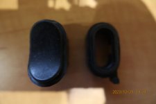
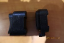
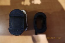
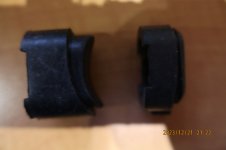
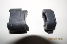
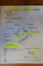
1) The long tiller handle has a rubber grommet in the factory casting for the optional switch which acts as a plug to keep water out of the handle. The idea is to remove the plug grommet and replace it with the power tilt switch 35640-ZW4-H11 and grommet 35643-ZW4-H02, simple enough except the new grommet doesn't fit. I'm attaching picture #1 of the two grommets to illustrate. The grommet on the left is the original rubber plug; on the right is the new 35643-ZW4-H02 grommet which I bought using an online supplier's Honda parts diagram for my BF30D5 BAUJ1100543. Picture #2 (from my Honda Service Manual) shows the shape of the grommet I need. The contours of the diagram picture of the grommet looks more like this than the one I received, which is too short to fill the gap between the switch and the casting. The grommet I received might be only one part of a two-part system but I'm guessing at that. I'm very unhappy with the online seller because apparently they don't provide "technical" support. Does anyone know about this or have a picture of the 35643-ZW4-H02 that differs from mine? Another thought is that 35643-ZW4-H01, the previous version to H02, might be what I really need.

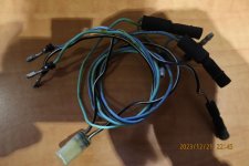
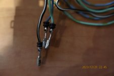
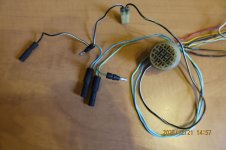
2) The base part of the wiring connector under the motor cover that supplies wiring to the long tiller handle doesn't have the light blue and light green wires that signal "down" and "up" operations. This might not be too big a problem for me since I also have the base part of the electrical harness from the scrapped motor and those two wires are intact, so I might be able to remove the crimped pins and wires if I understand how to do that bit of surgery. I'm not sure what wiring system this is and I'm hoping that someone here can enlighten me on this technology, how to remove and insert the pins and what tools to use. Picture #3 shows the base connector I'm using.

Thanks to one and all for any comments they may have.

Gary
 
Hi Gary,
No pictures yet.
This has stumped me too on this site in the past. I had success loading photos after downsizing them but not sure if that will work for you.
 
Thanks for the insight on pictures, jgmo. I did get one rejected because it was declared too big but all the others seemed to upload ok. Maybe I'll try downsizing pictures but afraid it will compromise quality.

Gary
 
Forgive me if I come up with things you've already considered.

Without seeing the pics though, I am thinking if the "plug" you have for the switch hole in the tiller can be hollowed out to accept the switch, that would be my first try to make a match. Doing things like that is one reason I always keep brand new Exacto Knife blades in my kit.

As far as moving the connectors in their housing, you will need to examine very closely how the retaining "latch" locks into the hole.

Usually you can figure out what you need to do by gently pushing and pulling on the wire and possibly using a magnifying glass to observe what holds the connector.

99.9% of the time they are initially inserted from the back of the connector housing and then latch so that they can't be pulled or pushed backwards.

It's usually two "ears" or barbs on the connector that snap into place and then spread outward to resist being removed.

The correct removal tools for almost any connector socket are readily available, inexpensively, on Amazon once you know what you need. However, you can often get by with using something skinny and stiff to fold the barbs in.

Again stuff you've probably already thought of but just tossing it out for discussion.

Good luck.
 
I see some people uploading photos to sites like photo bucket and then attaching here but no experience with that.
 
3rd attempt to upload pictures... thanks for interest!
Gary
 

Attachments

  • IMG_1344 resized.jpg
    IMG_1344 resized.jpg
    220.1 KB · Views: 2
  • IMG_1356 resized.jpg
    IMG_1356 resized.jpg
    264 KB · Views: 2
  • IMG_1355 resized.JPG
    IMG_1355 resized.JPG
    244.3 KB · Views: 2
I see some people uploading photos to sites like photo bucket and then attaching here but no experience with that.
Looks like photos are now available, jgmo. I used Photoshop Elements 7 to resize them to about half their original size (about 1.5 MB each).
 
Forgive me if I come up with things you've already considered.

Without seeing the pics though, I am thinking if the "plug" you have for the switch hole in the tiller can be hollowed out to accept the switch, that would be my first try to make a match. Doing things like that is one reason I always keep brand new Exacto Knife blades in my kit.

As far as moving the connectors in their housing, you will need to examine very closely how the retaining "latch" locks into the hole.

Usually you can figure out what you need to do by gently pushing and pulling on the wire and possibly using a magnifying glass to observe what holds the connector.

99.9% of the time they are initially inserted from the back of the connector housing and then latch so that they can't be pulled or pushed backwards.

It's usually two "ears" or barbs on the connector that snap into place and then spread outward to resist being removed.

The correct removal tools for almost any connector socket are readily available, inexpensively, on Amazon once you know what you need. However, you can often get by with using something skinny and stiff to fold the barbs in.

Again stuff you've probably already thought of but just tossing it out for discussion.

Good luck.
The hollowing-out option is a bit too ambitious for me, jgmo. Too much work and with my 76 years and declining eyesight I'd be almost certain to ruin the grommet. I'm sure there is the proper Honda grommet for this motor somewhere in the world but what it's part number is is what I'm trying to find out. The 35643-ZW4-H02 apparently fits quite a number of different Honda outboiards, even up to 70hp.

I've done work with automtive watertight connectors so have a few tools and a bit of experience. Knowing the type of connector and its system is my starting point. I'll try the inspect, probe, wiggle and gently coax approach if I can't determine the exact type of connector I'm dealing with. I doubt Honda will be bothered enough to tell me, though. Not enough in it for them.

Gary
 
One more picture... this shows trim/tilt switch installed without any grommet, so water can just pour in... unacceptable. Honda 35643-ZW4-H02 grommet, which is supposed to fit properly, is too short so a gap of at least 1/8" remains. So close yet so far!

Gary
 

Attachments

  • IMG_1345 resized.jpg
    IMG_1345 resized.jpg
    424.2 KB · Views: 1
Well, you've got a couple of years on me there but, having had my eyesight compromised for ALL of mine, I'm right there with you on that point :)
They wouldn't even consider my application for flight school:(
Probably why I'm such a LUNK when it comes to Tig welding too!

Anyway, I see your point about trying to find the correct part for the switch grommet. That WOULD be the best solution IF you could cross reference it. I don't have the answer but I KNOW that there will be many VERY smart and clever members probably reading this post so, hopefully, one of them will come up with that info for you.

Looking at the connector though, I do think it is an "insert from the rear" type but the latch is probably going to be more of a "ramp" type rather than the barbs I was talking about. That can work in your favor though since that type is typically pretty easy to release and typically only requires a flat, blade like tool to push the ramp from the top or bottom to get it to move past the "ledge" holding it.
I'm sure your prior experience with this stuff will get you past that problem.

A couple of other thoughts about getting the switch installed in case you can't find that grommet:

Honda got a little "too cute" with that switch hole IMO but you're stuck with it now.

Any youngsters in your family or friend circle with some artistic abilities? Convincing them to give hogging that grommet out might be my next move there. And why even worry about ruining it? At this point it isn't even a useful paper weight as is and is likely destined for the junk drawer or dust bin.

I have an excellent old fashioned hardware store in my town...good ol' HANK'S HARDWARE. That place has an amazing assortment of rubber plugs and grommets in their automotive section that I would probably be taking a look at to see if I could repurpose something there to work. Not your thing, I know, and not every town has a HANK'S but thought I'd mention it.

If worse comes to worse, you could actually just use a different DPDT (Double Pole Double Throw) momentary rocker switch and ....
A. Reconfigure that hole to fit it and a customized seal.
OR...
B. Plug that hole with the plug you already have and cut another one to accept the custom switch with weather seal.

I know most of my ideas won't appeal to you and that's ok. But, sometimes just kicking some ideas around can bring you to a solution that you can live with.

Looking forward to seeing how you "deal" with this and cheering you on for a reliable FIX.

Please keep us informed about what you come up with.

Good luck.
 
Thanks again, jgmo. I might try the hogging-out method you so practically suggest but only if I have a working model to follow. There is a metal bracket that sits in a wide groove on the backside of the rubber plug grommet to hold it firmly in place so the seal is tight. I've attached 4 more pictures of all sides of both grommets. Clicking on each picture should provide full size photos. I'm not so good with focussing my camera on close-ups but I think you'll still be able to see the vast differences between the plug grommet on the left and the switch grommet on the right in each shot. I'm hoping someone out there with a Honda outboard will have this trim/tilt option on the long tiller of their motor and could get me a picture of what a proper grommet installation looks like.

By the way, after a quick look at my connector I'm thinking you are probably right about the pin removal being quite simple. I'll have to get out my automotive pin probe to see if it will make this job as easy as I hope.

I really appreciate your interest!

Gary
 

Attachments

  • IMG_1364 resized.jpg
    IMG_1364 resized.jpg
    191 KB · Views: 3
  • IMG_1365 resized.jpg
    IMG_1365 resized.jpg
    178 KB · Views: 3
  • IMG_1366 resized.jpg
    IMG_1366 resized.jpg
    166.5 KB · Views: 3
  • IMG_1367 resized.jpg
    IMG_1367 resized.jpg
    153.2 KB · Views: 2
Big success for me on connector crimped pin & wire removal! As jgmo suggested, this job involved pushing down a plastic tab to release the small metal pin retainer and then the wire easily pulled free from the connector. The first trial was on a gray cable that I didn't care about but it worked so easily that I immediately went into production for the light blue, light green and black w/ white stripe wires that were my objective. Now all I have to do is install them into the empty slots waiting foir them in my working motor's connector. Assuming that'll work easily too, I'll then be down to only the trim/tilt switch grommet problem.

I've noit found out what this multiwire connector system used by Honda in 2005 outboard motors is called but sometimes you don't need to know what you're working on to be effective. Actually, I d still like to know!

Gary
 

Attachments

  • IMG_1371 resized.jpg
    IMG_1371 resized.jpg
    278.3 KB · Views: 3
  • IMG_1372 resized.jpg
    IMG_1372 resized.jpg
    213 KB · Views: 3
Back
Top