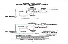
I am having issues figuring out the correct plumbing for my 318 log style manifold engine to set them up Full cooling. On Page 11 of the engine manual (I tried to attach but it would not accept PDF images) it has a diagram for LM318, M360 fresh water cooling system (full cool) has the fresh water side:
Leaving Heat exchanger, to bottom of manifolds, out top of manifolds, to water pump inlet through engine out T stat housing and back to heat exchanger.
The thing I don’t like about this set up is the coldest water is the heat exchanger (HX) outlet, this is because you have just transferred all the heat to the raw water in the HX. This diagram then has the water going through the manifolds which heats the water up, then to the motor. I would think you would want the coldest water going into the engine for maximum cooling.
I was surfing the web trying to get some pictures off full fresh water cooling and I found of a guy selling Chrysler marine engines, and he has a ton of pictures to get an idea of cooling hose set up. The website is http://harrysmarinerepair.com/index.php/chrysler-engines.html , . If you look at the first full cooling engine he is selling,He has the fresh water cooling set up like:
Fresh water HX outlet to engine water pump inlet, from water pump to engine, out T stat (T fitting) going to the bottom side of both EXhaust manifolds, out top of exhaust manifolds (connected to a T fitting) going back to heat exchanger to be cooled. The raw water side goes through trans cooler, through impeller pump, through HX, to both risers, out the back of boat. One thing about this configuration is it looks like if the engine T stat is closed no flow is going through the exhaust manifolds.
I was wondering if anybody else has full FWC what their plumbing configuration is, I just want to make sure I do it right. Something else about this set up is I see he has a small hose (3/8” or ½”) bypassing the T stat and sending flow back to HX, what is the purpose of this and I have not seen this on all engines?
Thanks
KMD