I had to replace some of the wires in my original engine harness as insulation was crumbling. p/n 84-73369.
I THOUGHT I replaced the wires with correct color coding, but now I'm second guessing myself (as engine is still having electrical issues even though it's got new stator, trigger, and switchbox).
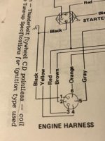
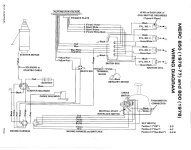
I'm confused by the Engine Harness wiring diagram in the SELOC manual (pg A-24) versus the harness that's in my motor.
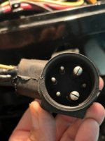
The harness has two large "pins" with one small one inbetween them on one side, and 3 small ones opposite.
Looking into the harness from outside the engine, the orientation of the illustration seems opposite of what's in my motor; namely, the two large "pins" in the illustration are on the left...versus my motor where they are on the right.
The SELOC manual shows
#1 (Black) large pin wire to ground and terminal on starter Solenoid
#2 (Brown) wire to Rectifier
#3 (Red) large pin wire to Starter Solenoid (battery post)
#4 (yellow) wire to starter solenoid
#5 (gray) wire to choke solenoid
#6 (orange) wire to switchbox (and to mercury switch)
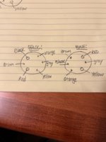
However, The harness in my engine has the following. Starting with the top large pin and going clockwise:
1:00 position: Large pin, RED wire
3:00 position: small pin, gray wire
5:00 position: Large pin, Yellow wire
7:00 position: small pin, Orange wire
9:00 position: small pin, Black wire
11:00 position: small pin, Brown wire
As virtually NONE of the color coding of wires corresponding to specific harness pins seems to line up between what's in my motor and what's in SELOC,
a) am I reading the SELOC diagram wrong?
b) is the SELOC diagram not correct for my motor (and if so, do you have a correct diagram you could send me?)
c) did I seriously mess up my color coding (and hence electrical connections).
I appreciate any guidance
(Sorry for the text; I have 3 photos I've been trying to upload...but the site keeps saying it's checking my browser and then goes blank...so I deleted photos to see if the text is successful in getting through).
Photos in post below.
Last edited:


