Logo

Yamaha 140beto V4 6f3 2 stroke wiring diagram

Hi, to whoever can help me out. I'm just done rebuilding my yam 140 beto 6f3 and ready to put the wiring back in place but can't find the correct wiring diagram to follow. I'm almost there but some of it isn't making sense. There's a few wires going places that don't really make sense at the moment. If anyone knows where I can find a diagram that guides me to the finish line then I would be really grateful. Thank you Richie
 
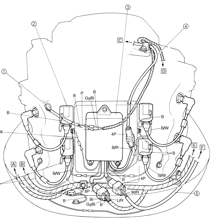
The service manuals for the V4 130 HP models issued in the USA have some diagrams in it that might lead you to where you need to be.
 
Hi Boscoe, I'm in Ireland. I have downloaded an e-manual that has a few diagrams in it and one in particular is "years through 1990". Its really old and impossible to follow when I expand it, it doesn't really stretch good. The engine is
Yamaha 140beto V4 6f3 2 stroke 450189.
I'll take your advice and try the 130 model diagram and see how that goes. Thanks for the reply, I appreciate it
 
Yeah I've got a few of those but there isn't really enough detail on them. There's a lot of wiring from thermostats, emergency switch box, trim switch, coil switchbox, oil reservoir level float switch. All need to be wired correctly I'm guessing to make the full circuit. The way I got it when I bought it, the main fuse is between the reservoir level connection and the switchbox and that doesn't seem right. Shouldn't that be going to the starter solenoid
 
Yeah I've got a few of those but there isn't really enough detail on them. There's a lot of wiring from thermostats, emergency switch box, trim switch, coil switchbox, oil reservoir level float switch. All need to be wired correctly I'm guessing to make the full circuit. The way I got it when I bought it, the main fuse is between the reservoir level connection and the switchbox and that doesn't seem right. Shouldn't that be going to the starter solenoid
That would be in the wiring diagram. Also in the manual. For instance

 
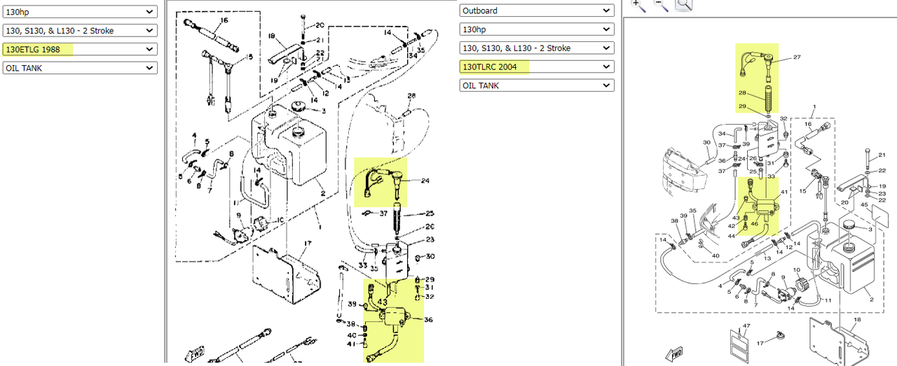
Thats bang on the money the way I'm thinking is usually done, but now I have a red wire from the emergency switch for the oil reservoir (on the engine) with nowhere to go. Does this just simply connect to the red on the starter solenoid. It would be activated by the float switch inside the reservoir. What manual are you getting the diagrams on, its a 1988 140beto but doesnt go into some menus like the sim.... Thank you for your time Boscoe its a big help
 
Thats bang on the money the way I'm thinking is usually done, but now I have a red wire from the emergency switch for the oil reservoir (on the engine) with nowhere to go. Does this just simply connect to the red on the starter solenoid. It would be activated by the float switch inside the reservoir. What manual are you getting the diagrams on, its a 1988 140beto but doesnt go into some menus like the sim.... Thank you for your time Boscoe its a big help
I am looking at a manual for a 1988 Yamaha USA 130ETXG.

https://www.simyamaha.com/search/?search_query=LIT-18616-00-41

 
Right, my bad. I can follow the diagram with the starter motor, solenoid, fuse and ignition. I'll go with that and see if it turns over the starter motor. Then I'll try adding the tilt and trim. Then I'll try the emergency switch box connected to the oil reservoir-this also has wiring for the pump on the main oil tank(boat), the tilt and trim indicator and the rev counter/oil level warning. The manual i have here for it is printed in Japan in 2005 for E115A, 115B and 140B. It must be the right one unless its been altered over the 30-odd years of use. I'll keep trying, no choice. Thanks again Boscoe
 
No, sorry its the 140b manual I have for it. Its old style but the serial number matches the manual. Its just the drawings are really old style and even when blown up they have all black lines going across each other.. I asked a marine expert store and gave him the serial number and he said its was a 1988 engine.
 
No, sorry its the 140b manual I have for it. Its old style but the serial number matches the manual. Its just the drawings are really old style and even when blown up they have all black lines going across each other.. I asked a marine expert store and gave him the serial number and he said its was a 1988 engine.
I would bet that your 1988 140B model is the same as a USA 1988 130 model.

A USA 2005 130 is not wired the same as a USA 1988 130. So why be using a 2005 service manual for your 1988 model year motor?

By serial number, your 6f3 450189 is a 1998 model year motor.

 
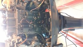
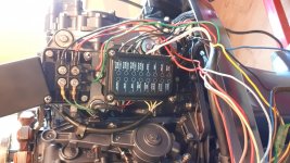
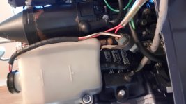
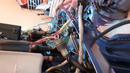
Ok now we're getting somewhere. I bet he put in 88 instead of 98. Mistype? Anyway, I don't have a cdi unit like the ones mounted on the back of the water jacket at the back of the engine. The 4 coils are mounted on the back of the engine and the switch box is mounted on the starboard side running to the coil wires. I'm gonna try post a picture of it for you
 
Oh man, I'm really going the tough way about this. For some reason my photos are mirrored making it the port side look like starboard and vice versa. Please forgive me, you must be on prozac by now, I'm sorry. No cdi unit as such but a switch box and regulator on one side. Coils on the back and the emergency switch box and starter solenoid on the port side. Can you make any more of it now. Don’t mind the colour, I repainted it recently. It was old blue yamaha colour before
 
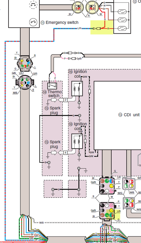
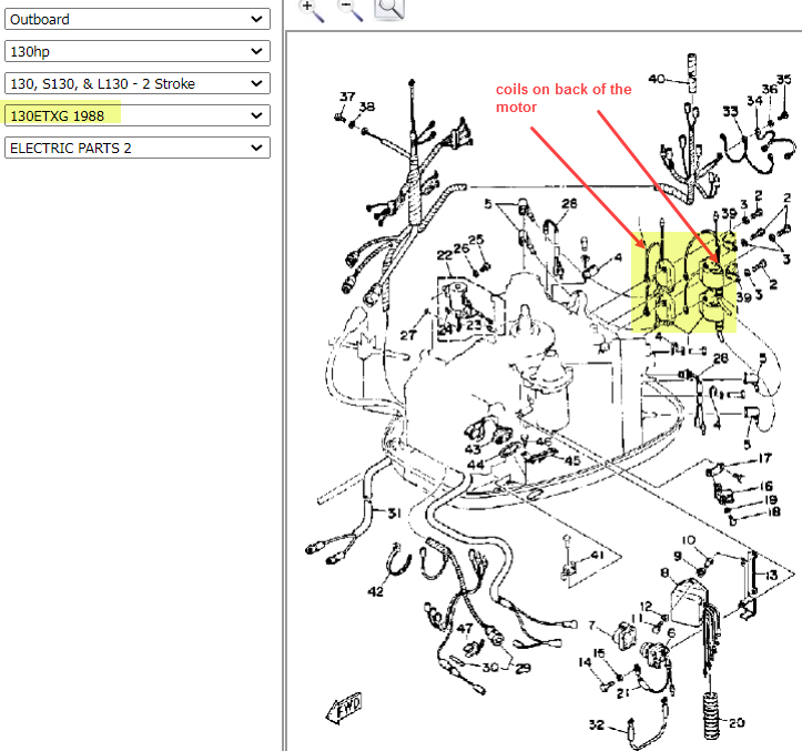
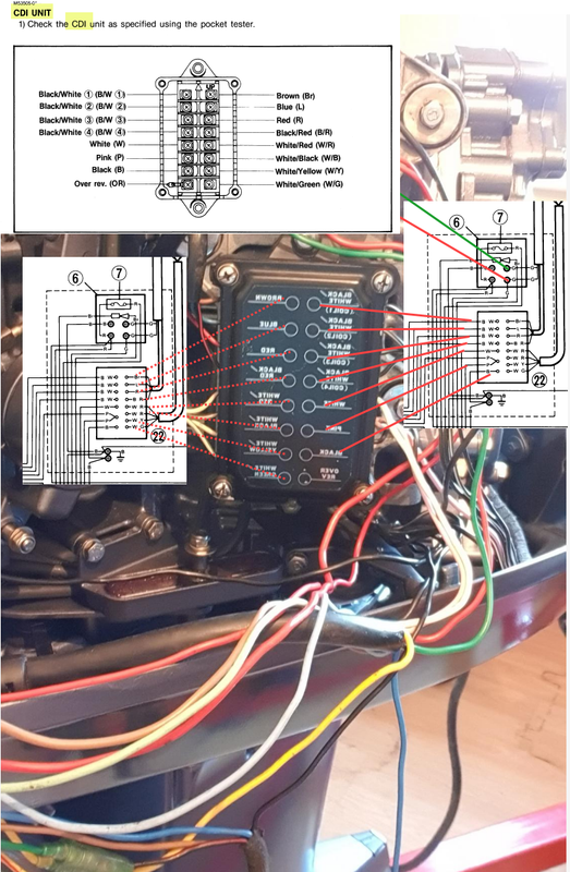
The insert that I added to your photo is from the 1988 USA 130 manual.

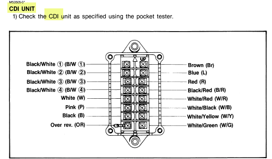
The gizmo below the regulator/rectifier with all of the wire colours printed on it is known by Yamaha as a CDI assembly. Capacitance Discharge Ignition assembly.

 
Last edited:
Thats bang on, 100%. I'm in the process of wiring it from the diagram in the download of the 1988 130 USA and its one diagram and much clearer than what I had. The engine was running when I purchased it so I'm guessing all the electrics are ok.
Thanks for all your help Boscoe, this should do it 👍
 
Back
Top