Logo

Alpha One Gen One yoke shaft resistance

Dterry

Contributing Member
Hey all,

I am in the process of rebuilding my alpha one sterndrive and I am following along with the service manual. I have completed the shimming procedure using the appropriate tools for the drive gears in the upper housing. Also, I have made sure that the proper torque has been set for the upper driveshaft, cap, and lock nut on the drive gear assembly. After assembly was complete for the upper housing I noticed some resistance when trying to spin the yoke shaft, am I suppose to have some resistance or should I be able to spin it with minimal effort?

Best, Dan
 
""I have made sure that the proper torque has been set for the upper driveshaft, cap, and lock nut on the drive gear assembly.""


Saying you followed the proper procedure does not mean you followed the proper procedure. The key unknown is the NUT on the drive gear assembly would be suspect to me.

There are two procedures based on drive shaft design. One, there is a large spacer between bearings and for this you torque to spec. No spacer you do a rolling torque to spec. Which do you have? Do you know? What spec did you use?

With the upper gear case all assembled, of course there will be resistance. How much cannot be described from a key board.

You say you shimmed and used appropriate tools................OK what shims and what tools? What spec did you follow for the Cap?

Do you have the gear depth measuring tool? If so did you use the correct measuring location on it? These are things we have no idea if you have or did correctly

Remember you saying you did something but not telling us what specifications you followed or manual you followed tells us nothing.
 
Saying you followed the proper procedure does not mean you followed the proper procedure. The key unknown is the NUT on the drive gear assembly would be suspect to me.

There are two procedures based on drive shaft design. One, there is a large spacer between bearings and for this you torque to spec. No spacer you do a rolling torque to spec. Which do you have? Do you know? What spec did you use?

  • Its the second procedure; the drive shaft bearing does contain a larger spacer but not the smaller spacer you are thinking. That spacer is smaller and sits in between the two bearings and requires 85 ft-Ibs of Torque to the Locking Nut. Instead I used a rolling torque of 6 in-Ibs to the Locking nut, and i believe the range is 4-10 in-Ibs.

With the upper gear case all assembled, of course there will be resistance. How much cannot be described from a key board.

  • Understood but should i be able to spin it with one finger or will I need two hands on it with some good pressure to turn it?
​You say you shimmed and used appropriate tools................OK what shims and what tools? What spec did you follow for the Cap?

  • Shimming tool C-91-36384 and C-91-60523
  • Shims GLM 23280, 23210, 23260
  • Cap torqued to 20 ft-Ibs

Do you have the gear depth measuring tool? If so did you use the correct measuring location on it? These are things we have no idea if you have or did correctly

  • In the appendix there is a chart in which says i should be using the "Z" surface (ratio is 1.5:1) on the shimming tool and i shimmed to a distance of 0.025 with the feeler gauge.
  • Before shimming the drive gears I set the rolling torque of the vertical drive shaft to 6 in-Ibs with the spec states should be in between 4-10 in-Ibs. And yes i removed the oil seals before doing so to prevent in accurate readings.

Thanks for the comments, Dan.

 
Last edited:
If this is only the upper unit, you have a problem.
If with the complete unit ,normal cause your turning the impeller also
 
Yes I meant the small spacer.

What did you torque the large spanner nut at drive shaft/yoke area to? The one that uses that big special wrench.

Did you follow the torque spec based on length of torque wrench? Typical 1/2" drive torque wrench is 18"-19" measurement used to determine, and so the typical torque used is 120-123 Lbs/Ft


Saying you followed the proper procedure does not mean you followed the proper procedure. The key unknown is the NUT on the drive gear assembly would be suspect to me.

There are two procedures based on drive shaft design. One, there is a large spacer between bearings and for this you torque to spec. No spacer you do a rolling torque to spec. Which do you have? Do you know? What spec did you use?

  • Its the second procedure; the drive shaft bearing does contain a larger spacer but not the smaller spacer you are thinking. That spacer is smaller and sits in between the two bearings and requires 85 ft-Ibs of Torque to the Locking Nut. Instead I used a rolling torque of 6 in-Ibs to the Locking nut, and i believe the range is 4-10 in-Ibs.

With the upper gear case all assembled, of course there will be resistance. How much cannot be described from a key board.

  • Understood but should i be able to spin it with one finger or will I need two hands on it with some good pressure to turn it?
​You say you shimmed and used appropriate tools................OK what shims and what tools? What spec did you follow for the Cap?

  • Shimming tool C-91-36384 and C-91-60523
  • Shims GLM 23280, 23210, 23260
  • Cap torqued to 20 ft-Ibs

Do you have the gear depth measuring tool? If so did you use the correct measuring location on it? These are things we have no idea if you have or did correctly

  • In the appendix there is a chart in which says i should be using the "Z" surface (ratio is 1.5:1) on the shimming tool and i shimmed to a distance of 0.025 with the feeler gauge.
  • Before shimming the drive gears I set the rolling torque of the vertical drive shaft to 6 in-Ibs with the spec states should be in between 4-10 in-Ibs. And yes i removed the oil seals before doing so to prevent in accurate readings.

Thanks for the comments, Dan.

 
Hey Jack the manual calls for 200 ft-Ibs, maybe that's a little over-kill?

Dan


Yes I meant the small spacer.

What did you torque the large spanner nut at drive shaft/yoke area to? The one that uses that big special wrench.

Did you follow the torque spec based on length of torque wrench? Typical 1/2" drive torque wrench is 18"-19" measurement used to determine, and so the typical torque used is 120-123 Lbs/Ft
 
Hey Jack the manual calls for 200 ft-Ibs, maybe that's a little over-kill?

Dan

Dan

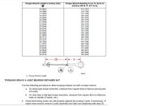
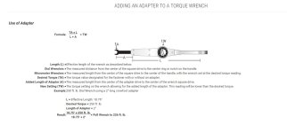
If you look at the image Chris uploaded you can see the torque "multiplier" explanation shown by the dimensions of the torque wrench and tool combined.

The desired final torque spec is 200 LB/FT BUT when you follow the diagram based on the specific length of the tool combined with the specific measured length of the torque wrench the actual setting on the torque wrench has to be set much lower as the total length of both tool and wrench create a "Multiplier"

So Measure your tool (and not the one between your legs) and the torque wrench based on Chris's image and then use the chart from image to select the correct torque wrench setting and redo your nut tightening!

Here is the actual formula

see image

Carl torque.JPG
 
Back
Top