Logo

Mercruiser 4.3 w/ TKS fuel pump runs 24/7

cjanech

New member
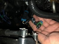
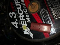
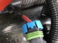
Hey team - long time reader, 1st time poster here. I have a 2006 Bayliner with a 2005 Mercruiser 4.3l with TKS. Not too long ago, the oil pump shaft sheared (yep sheared) and the oil pump quit. I had my mechanic pull the engine & replace the oil pump. Put it back in the water and runs like a champ! About a month ago, he dropped off the boat and within the past week, I was working on getting it ready for the season. I went to turn the key, no power. BTW - the battery was replaced when the oil pump was replaced. I hooked the [COLOR=#67B045 !important]charger[/COLOR] up and it turns out the battery was dead. Odd since the battery was new. I turned the key to on and there was power to the dash. Turned the key off and could hear a noise coming from the engine bay. It was my fuel pump. It runs 24/7 with the key on or off. I removed the maroon TKS diode and the pump shut off so that I could charge my battery and avoid an unsafe [COLOR=#67B045 !important]condition[/COLOR]. Plug the diode in, fuel pump starts up regardless of key position. One more thing to add...before I realized the battery was dead, I checked all of the [COLOR=#67B045 !important]fuses[/COLOR]. The only bad [COLOR=#67B045 !important]fuse[/COLOR] I could find was the 20a fuse in the plug that is located next to the diode plug. Any thoughts? Thanks! Chris
 
I'd be inclined to call the mechanic ... and explain the situation and ask him to resolve it...

could be the diode shorted or the wiring got fouled up...
 
....or perhaps the mechanic hot wired the fuel pump to run the engine to diagnose oil pressure problem... NORMALLY... no oil pressure no fuel pump run,
 
What makes you "think" its the issue?

Diodes when testing with an ohm meter are like an ON / OFF device.

With meter leads connected there should be ohms and when reversed there should not be.

So either you see ~ 300 ohms with meter leads connected as shown in procedure and infinity when leads are reversed.

If you see ohms in both directions with leads reversed or infinity in both directions, Diode is bad


Exactly that. I show resistance in both directions. No infinity.
 
Exactly that. I show resistance in both directions. No infinity.

Per instructions that Chris added

One failure mode is,

the diode is shorted internally and will pass current both ways

This is what you are seeing.

My opinion....................SH!TTY Diodes.............Most likely to close to specified voltages and unable to handle voltage/current spikes (no spike protection).

You get what you pay for...........This is obvious due to the technical bulletin.............WAY TO GO MERC!!


Sorry for the late reply (to all), but I finally got the new diode installed and that was exactly the issue. It was a crappy diode. However, my battery is still draining. Not draining as fast as it was with the faulty diode and not sure if this is a separate issue or related. I've got the issue isolated to the engine bay by disconnecting the lead to the main fuse box on the dash and I dropped 1 volt in 2 days (12.65 down to 11.65). Guess I've got to probe around to see what is using current...ughh!
 
Disconnect all connections to batter including the Positive battery cable,

Connect volt meter, one lead to battery and one lead to cable.
connect meter leads at meter to amp ports and Set meter to AMPS

See what amp draw is..

It has been a while but if I remember correctly it should be below .24 amps (1/4 amp).

If higher than that start disconnecting things until it get to or below that number.

Start with large engine connector to separate dash from engine.

Got it! Is there a preference on negative or positive post on the battery as I'm checking leads?
 
Positive battery connection. Amp meter with leads in Amp locations only.

Leave ground connections as is.
 
First, you missed my point/question.

What color wires are going to fuse? Schematics show wire color not connector color

did you install the diode in the correct polarity? That is important!

I am not all that familiar with the TKS wiring.

So if you disconnect fuse, battery drain stops?

I looked at what I have for TKS wiring and if I saw it correctly, The power which goes to fuse is through a red with purple colored wire. I think that wire goes to starter solenoid for its power. So that would tell me that the starter solenoid terminal is either Battery + (power all the time) or power when cranking only (depends on which solenoid terminal wire is attached to)

Follow wires if you can and see where they go.........

Has the starter been replaced or worked on recently? Is there another wire attached at solenoid that may not belong there?
 
First, you missed my point/question.

What color wires are going to fuse? Schematics show wire color not connector color

did you install the diode in the correct polarity? That is important!

I am not all that familiar with the TKS wiring.

So if you disconnect fuse, battery drain stops?

I looked at what I have for TKS wiring and if I saw it correctly, The power which goes to fuse is through a red with purple colored wire. I think that wire goes to starter solenoid for its power. So that would tell me that the starter solenoid terminal is either Battery + (power all the time) or power when cranking only (depends on which solenoid terminal wire is attached to)

Follow wires if you can and see where they go.........

Got it. Sorry, I'm at work and those were the only pictures that I had. I'll check this afternoon.

The diode can only go into the plug 1 way, so that should be correct.

Yes, when I disconnect the fuse the amps drop to 0.

I did have some starter work done recently. Hmmm...might be on to something. Thank you!

Has the starter been replaced or worked on recently? Is there another wire attached at solenoid that may not belong there?
 
First, you missed my point/question.

What color wires are going to fuse? Schematics show wire color not connector color

did you install the diode in the correct polarity? That is important!

I am not all that familiar with the TKS wiring.

So if you disconnect fuse, battery drain stops?

I looked at what I have for TKS wiring and if I saw it correctly, The power which goes to fuse is through a red with purple colored wire. I think that wire goes to starter solenoid for its power. So that would tell me that the starter solenoid terminal is either Battery + (power all the time) or power when cranking only (depends on which solenoid terminal wire is attached to)

Follow wires if you can and see where they go.........

Has the starter been replaced or worked on recently? Is there another wire attached at solenoid that may not belong there?

It’s a red with blue stripe and solid orange wire.
 
Are you color blind............Red with Purple stripe, This is a standard Mercruiser color.

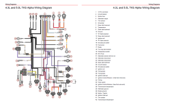
Based on the schematics I looked at the other wire going to the fuse connector should be Black with yellow stripe.

The schematics I have do not show all the connections only the basic harness as on the engine. so I can't see where they connect to from there.

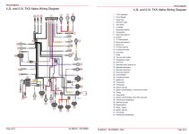
I am not on my pc right now (working for a living) so when I get home I will upload a copy of the schematic I have from a merc manual for TKS carb systems.
They show OEM and an adapter harness if you switch to TKS from normal carb. Not that anyone would ever do so as this TKS system just SUCKS.

Not that I’m aware of. There are a few purple wires around the area and the stripe is a far departure from purple. But, I’ll take your word for it. I’m not familiar with Mercruiser wiring, or what’s standard or not. I appreciate the help. Thanks.
107B1F45-6959-41BA-810F-D7C491F611E6.jpeg
 
Here is all I have, Maybe someone else has more.

v6 tks.png
 

Attachments

  • TKS 4 3 .png
    TKS 4 3 .png
    97.1 KB · Views: 64
Last edited:
As I am not familiar with TKS I can only guess...................

Here is my thoughts, If power is going to the fuse, Is it supposed to be there all the time?

Once we understand this we can understand why it may be the reason for your battery drain.

Red with Purple wire is Battery +,

One Main power connection from Main terminal on starter is a Red wire which goes to main engine breaker (in) and then Red with purple wire (out) which feeds many things including ignition switch and TKS thru fuse 20 and Alt (sense I think)................etc.

So that means that the fuse connection 20 is HOT all the time. +12 volts (battery voltage). It should be!

That is not your problem. Your problem is why that power going to the TKS, being asked for when KEY is off.

So either the diode you installed is bad (YOU did not disconnect power before installing) and your power drain is thru a shorted diode or something else in that circuit is calling for power when it should not be.


So unless someone else chimes in and can assist I have no other thoughts

I have to say, who ever agreed that that schematic was worth a sh!t was a fool. It should be a standard full assembly/point to point schematic as used in every engine manual they have ever produced!
 
Last edited:
thanks Jack. Perfect!

As an update, the new diode was bad and replaced. I was up and running for a short period of time on the lake and popped a fuse under the dash and the boat shut down. Replaced the fuse and limped back to the dock. After further diagnosis, the temp sending unit that works with the TKS and plugs directly into the intake manifold was bad (high resistance). Just installed the new one tonight and ran it for 30 minutes in the driveway. Perfect! I bumped the idle a bit to make sure it got up to, and maintained a good temperature. Everything worked perfect. So, I turned the key off, and it kept running. Tried to pull the safety tether and nothing. Tried to trip the breaker...nothing. Pulled all the fuses under the dash...nothing. Pulled the leads off the ignition switch, nothing. Disconnected the battery...nothing. Disconnected the new thermal switch installed and the 20a fuse that is associated with the TKS...nothing. I had to pull the coil wire to shut it down. This is starting to get comical (not really).
 
As an update, the new diode was bad and replaced. I was up and running for a short period of time on the lake and popped a fuse under the dash and the boat shut down. Replaced the fuse and limped back to the dock. After further diagnosis, the temp sending unit that works with the TKS and plugs directly into the intake manifold was bad (high resistance). Just installed the new one tonight and ran it for 30 minutes in the driveway. Perfect! I bumped the idle a bit to make sure it got up to, and maintained a good temperature. Everything worked perfect. So, I turned the key off, and it kept running. Tried to pull the safety tether and nothing. Tried to trip the breaker...nothing. Pulled all the fuses under the dash...nothing. Pulled the leads off the ignition switch, nothing. Disconnected the battery...nothing. Disconnected the new thermal switch installed and the 20a fuse that is associated with the TKS...nothing. I had to pull the coil wire to shut it down. This is starting to get comical (not really).

wow, i got nothing to add at this time but i am looking forward to reading what you find.
 
I worked on military HAWK SAM missile range radar, search radar and fire control. Corrosion in high moisture environments caused all kinds of problems that would get me called out at 2 a.m. on a Saturday night. The boat is 16 years old so expect to find bad connections. Clean all electrical connections that appear blue-green (copper corrosion) or white and powdery. Make the copper shine like a new penny then coat lightly w/electrical grease or any metal free grease. The corrosion can grow in minute lines hard to see and make a short to ground or another circuit causing all kinds of odd problems. When you come across any ground wire...clean it, grease it and reinstall.
 
I worked on military HAWK SAM missile range radar, search radar and fire control. Corrosion in high moisture environments caused all kinds of problems that would get me called out at 2 a.m. on a Saturday night. The boat is 16 years old so expect to find bad connections. Clean all electrical connections that appear blue-green (copper corrosion) or white and powdery. Make the copper shine like a new penny then coat lightly w/electrical grease or any metal free grease. The corrosion can grow in minute lines hard to see and make a short to ground or another circuit causing all kinds of odd problems. When you come across any ground wire...clean it, grease it and reinstall.

thanks a ton for the feedback. I was thinking that this has to be a bad ground somewhere. Also, this boat has spent most of its life in Charleston. Saltwater probably hasn’t been too kind.

thanks! Chris
 
If you find you need to make a new connection when you strip the plastic off the wire you will find either marine grade tinned wire and little or no corrosion or more likely find blackened copper wire which is corrosion. It can be cleaned with 200 or 400 grit sandpaper. I fan the wire so it looks like a leaf rake then squeeze the wire between folded sandpaper. Continue to roll and fan the wire and clean it before making the new connection. A little grease helps when done. Solder won't stick to the blackened wire; it has to be clean copper and dipped in flux first.
 
Posting this in case someone else has this issue. I’ve got a 2008 Bayliner with a 4.3L Mercruiser engineer that I bought used 5 yrs ago, it has about 400 hrs. Over the last year I would turn off the engine and sometimes it would run intermittently then shut off, which I thought was due to a warm engine and uncombusted fuel (my first boat). Yesterday it wouldn't shut off, the ignition was off, no power. I got lucky, pushed the 50A breaker and it shut down. I flipped the breaker back on and the something started running (fuel pump?). I keep it in N GA and the mechanic I used stopped servicing inboard/out boards so I need to figure it out. I read this thread and a couple of others and it looks like it’s the TKS diode. I found the location, left of the carburetor, red and purple wires, green band partially hidden by black housing. I ordered a new one and will try to replace it next week.
 
Back
Top