Logo

Volvo AQ280 Electric Drive Lift Issues

G-Man24

New member
Hi all. I've been following the forum for some time now to glean more info on my VP AQ280 drive and related service requirements. I'm astounded at the level of expertise found here. I recently joined as a member as I could really use some help on this issue and I'm hoping some of the experts like Rick will chime in . (Please excuse me if I get some of the nomenclature wrong. The little experience I've had with drives in the past was with MerCruiser this is the first VP I've owned or worked on.

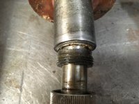
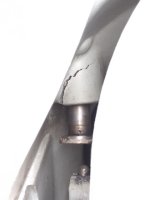
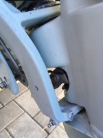
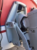
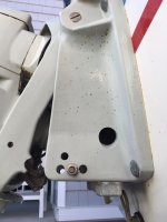
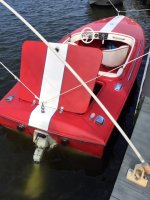
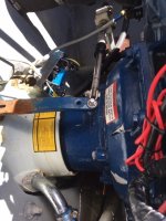
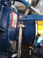
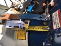
For some background this is a 1978 Donzi 18 ft (2+3) with a Ford 351W Commander/ AQ280 package. When I first got the boat I replaced the U-Joints & bellows by removing the upper drive gear unit . While working on it I happened to notice the lift's round foot (pressure plate) was contacting the thrust sleeve/release rod at a location that was far off center. I thought maybe that was normal and it centered itself better as the drive lifted and since it all worked fine for most of the season I didn't give it much thought. Now however I have run into a serious problem. While running in shallow water last weekend I could feel the boat running aground and tried to operate the lift to no avail. Would not move up or down. When I pulled the boat out on the ramp I realized the latch was not releasing even though the drive was all the way down. I managed to release it using a screwdriver and after lifting slightly I could see where the thrust sleeve and ridden completely off the pressure plate and was trapped behind it. Further examination showed the lift had a bent shaft and worse now had developed a crack in the housing (transom plate? ) where the lift shaft exits. (see photo 4)

I managed to unscrew the distorted pressure pad and remove the lift mechanism. The end of the housing where the sealing nut threads on is cracked off. I have not completely disassembled it yet but at this point I'm looking at a new housing, new shaft and pressure plate at the very minimum. I can deal with all that. My biggest concern though is the crack in the transom plate. This boat is all original and in beautiful condition so the prospect of pulling the motor or having to tear all the running gear off the transom to fix that crack has me freaking out a bit.

If I clear enough room by removing the upper drive/ helmet, etc. I think it would be accessible enough for a good welder to reach in and tig the crack shut. Does this sound like a workable idea ? If so should I attempt to push the crack closed before welding or fill it in the way it is ? I'm guessing if I don't push it back the O-ring on the sealing nut may not seal as the bottom of the bore will no longer be perfectly round.

Looking forward to your replies and suggestions.

Gerry
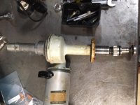
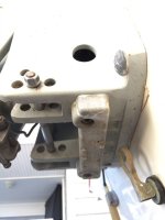
IMG_2675.JPG IMG_2674.jpg IMG_2673.jpg IMG_2669.jpg
 
.....................
Hi all. I've been following the forum for some time now to glean more info on my VP AQ280 drive and related service requirements. I'm astounded at the level of expertise found here. I recently joined as a member as I could really use some help on this issue and I'm hoping some of the experts like Rick will chime in . (Please excuse me if I get some of the nomenclature wrong. The little experience I've had with drives in the past was with MerCruiser this is the first VP I've owned or worked on.

For some background this is a 1978 Donzi 18 ft (2+3) with a Ford 351W Commander/ AQ280 package.
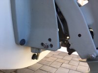
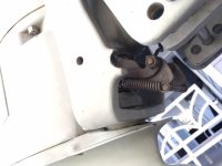
How many of these black rubber hooks exit the lower area of the transom shield?
One or two?
vp0843235.jpg

If only one, you have a easily obtainable transom shield.
If two, you have a rather difficult to find transom shield.


When I first got the boat I replaced the U-Joints & bellows by removing the upper drive gear unit . While working on it I happened to notice the lift's round foot (pressure plate) was contacting the thrust sleeve/release rod at a location that was far off center. I thought maybe that was normal and it centered itself better as the drive lifted and since it all worked fine for most of the season I didn't give it much thought. Now however I have run into a serious problem. While running in shallow water last weekend I could feel the boat running aground and tried to operate the lift to no avail. Would not move up or down.
First off, this unit is a lift out unit only and is to be used to raise the drive when trailering, etc.
Only upon rare occasions would it be used to raise the drive when in shallow water, and only under very low engine power.


When I pulled the boat out on the ramp I realized the latch was not releasing even though the drive was all the way down. I managed to release it using a screwdriver and after lifting slightly I could see where the thrust sleeve and ridden completely off the pressure plate and was trapped behind it. Further examination showed the lift had a bent shaft (that is the vice rod) and worse now had developed a crack in the housing (transom plate? ) where the lift shaft exits. (see photo 4)
Yes, very typical when used as a trim unit during powering-up.

I managed to unscrew the distorted pressure pad and remove the lift mechanism. The end of the housing where the sealing nut threads on is cracked off. I have not completely disassembled it yet but at this point I'm looking at a new housing, new shaft and pressure plate at the very minimum. I can deal with all that.
If interested, I have complete (minus the electric motor) units available.

My biggest concern though is the crack in the transom plate. This boat is all original and in beautiful condition so the prospect of pulling the motor or having to tear all the running gear off the transom to fix that crack has me freaking out a bit.
Unfortunately, there is no other option..... unless you abandon the lift out unit and block off the opening.

If I clear enough room by removing the upper drive/ helmet, etc. I think it would be accessible enough for a good welder to reach in and tig the crack shut. Does this sound like a workable idea ?
The bore would need to be in near pristine condition in order for the outer O-ring to form a good seal.
I suppose that you could give it a try........ but I doubt that it's worth it when you can pick up a good clean single relief transom shield for very little.

s-l300.jpg


If so should I attempt to push the crack closed before welding or fill it in the way it is ? I'm guessing if I don't push it back the O-ring on the sealing nut may not seal as the bottom of the bore will no longer be perfectly round.
correct!

Looking forward to your replies and suggestions.

Gerry
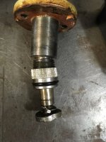
View attachment 25231 View attachment 25230 View attachment 25234 View attachment 25238
 
Rick thanks so much for the informative reply. I suspect the previous owner may have used the lift as "power trim" and I was guilty of doing the same at slow speed. I had no idea it was only to be used for trailering. Lesson learned.


A couple other questions....If all parts are functioning and aligned normally, should the thrust sleeve contact the pressure plate exactly in the center when the drive is in the lowered position?

Second...is it possible to swap out the transom shield without removing the engine if you support it somehow ?

I cannot find any of the black rubber hooks you referred to. Are they all the way on the bottom by the zinc block ? I have attached some additional photos to maybe help identify it.

Thanks again for your help.

Gerry

IMG_2678.JPG IMG_2686.JPGSteering fork1.jpg Transom plate 1.jpg Transom plate 2.jpgTransom plate 3.jpg
 
Last edited:
...................
Rick thanks so much for the informative reply.
You are very welcome.


A couple other questions....If all parts are functioning and aligned normally, should the thrust sleeve contact the pressure plate exactly in the center when the drive is in the lowered position?
If not exactly, it should be close.

Second...is it possible to swap out the transom shield without removing the engine if you support it somehow ?
Short answer...... Yes.

I cannot find any of the black rubber hooks you referred to. Are they all the way on the bottom by the zinc block ? I have attached some additional photos to maybe help identify it.
I see from your photos that your transom shield is a single exhaust relief unit, and that the relief was not used.
You most likely have thru-transom exhaust!
If so, this means that a 4 cylinder transom shield could be used.
Fortunately, those are not in demand and should be inexpensive to buy.


FYI....
The 4 cylinder 280 and 275 shields use the collar steering fork with the large diameter shaft and also use the larger rubber bumper.
The 270 and earlier use the
collar steering fork with the small diameter shaft and use the small rubber bumper.

Use caution.... not all sellers accurately describe their Volvo Penta parts, often using the wrong names or model numbers.


If you replace it, be sure to also replace the large inner rubber cushion ring. The inner ring provides the water seal.
Also replace the 6 fat O-rings that seal the carriage bolt shanks.

Tip:
When you remove the drive, remove the transmission first, then the suspension fork hinge pins and the remaining portion.
When going back together, do the reverse of that.

If you are running an s/p drive, use 30W engine oil for gear lube.
If you are running a DP drive, use the correct GL-5 for gear lube.


Let me know if you have any interest in that Lift-Out unit that I have.
 
Last edited:
Yes on the thru-hull exhaust, large diameter steering fork shaft and large rubber bumper. I'm familiar with removing the transmission/upper gear case first as I followed your old posts and used that method when replacing my universal shaft bearing crosses and the bellows.

PM sent for parts.. thanks !

Gerry


78 Donzi.jpg
 
...............
Yes on the thru-hull exhaust, large diameter steering fork shaft and large rubber bumper. I'm familiar with removing the transmission/upper gear case first as I followed your old posts and used that method when replacing my universal shaft bearing crosses and the bellows.

Have you replace the PDS bearings yet?
If not, and if you replace the transom shield, it would be a great time to do it.
 
.Have you replace the PDS bearings yet?
If not, and if you replace the transom shield, it would be a great time to do it.

I picked up a rather mysterious vibration towards the end of the season that I was having trouble tracking down. It's most prominent between 2500-3000 RPM but seems smooth up to and beyond that RPM range. Cross bearings and bellows are new this year. I was thinking I might have tweaked the prop hitting bottom but could be the PDS ?

Likely the PDS is the Holman-Moody extended style and the issue of open vs sealed bearings and lube fitting may apply...

Thanks for looking in Capt. Bob. I would love to say this boat was Hollman Moody equipped but it's not. All of the marine related equipment on the 351W (exhaust manifolds, engine mounts, flywheel housing, etc...have the name "COMMANDER" cast into them. I do not see any zirk fitting or passageway that would facilitate the greasing of the PDS bearing. It's hard to believe it's designed so you have to pull the engine or transom shield just to replace them because they ran out of grease.

I did happen to take a peek at the back of that bearing when I had the upper drive unit off and it was a sealed bearing...FAG 6206 RS

(BTW you may have seen my boat this past summer from your perch up on Island Heights. I cruise up Toms River all the time and was over there just a week ago before I pulled the boat out. I like looking at the old Victorians and that big Gazebo/Bandstand structure by the yacht club.)

Gerry
 
Last edited:
Hollmn-moody "Style" intermediate wherein the engine is a standard "bobtail" engine with a Borg-Warner bolt circle flange, connected to a separate extended intermediate housing ( about 4 " longer than standard)... My Chris Craft came equipped with that setup. It allowed Chris Craft to use stock Chris Craft marinized and branded engines in front of a Volvo drive.

Re: bearings... This housing has two bearings wherein the inner facing bearings have either sealed or no seals.... If no seals, the housing has a zerk fitting which allows lube of the bearing without taking them apart.

Think I've seen you on the bay. Not that many small Donzis on the bay...
 
Gerry, your part is boxed up and ready to ship. I'll get it out today.


Regarding the PDS and housing, Donzi often used their own "B/W to V/P PDS adapter housing", but it's possible to see the Holman Moody, Eaton, Glastron, ChrisCraft or other brands/makes being used.

My experience with these is that they all position the engine further forward by 3 - 1/8".

I've seen them with a double bearing PDS, and I've seen them with a single bearing PDS w/ a pilot nose.
Since you have the 335 series Ford engine, your PDS is most likely a single bearing with a pilot nose.

The double bearing PDS adapter housing will typically have a means of greasing the bearings.
The single bearing PDS will typically used the sealed bearings.

I've seen these with the AFT bearing being a 6206 and I've seen them whereby a smaller AFT bearing was used.

You'll simply need to pull things apart in order to know which system you have.

I do recall that you said the AFT bearing was a 6206-2RS, of which is a sealed bearing.


Here is a 335 series Ford Borg Warner flywheel cover with a Volvo Penta B/W to V/P PDS adapter housing attached.
I found this in one of my own posts in this old thread
http://www.marineengine.com/boat-forum/showthread.php?430996-small-rattle-noise-in-the-275-gear-box


This combination profile is identical to the Volvo Penta 335 series Ford 1 pc flywheel cover, as it does not move the engine forward.
NOTE the grease port screw @ 12:00 O'clock.

attachment.php
 
Last edited:
Well based on what I see in your post Rick it looks like I have the extended adaptor housing with the double bearing. NO grease port or zirk fitting. The flywheel cover is approx. 3" deep and the adaptor housing is another 4" to where the Volvo housing begins. (See pics)

Drat! I did not want to deal with the double bearing if it requires backing up the engine or removing it. Any chance they will both come out from the aft side ?

On the positive side, thanks to Rick I have a replacement lift assembly on the way. I really appreciate all the help he's been giving me.

Thanks also to Capt. Bob for the input. This forum is a great resource of knowledge.

Gerry

adaptor1.jpg adaptor2.jpg View attachment 25274 adaptor4.jpg
 
Last edited:
...................
Well based on what I see in your post Rick it looks like I have the extended adaptor housing with the double bearing.
It's the extended unit alright........., but you won't know about the single vs double bearings until you disassemble it.

NO grease port or zirk fitting.
Typically, the absence of the grease port indicates a PDS with a single sealed bearing.
If you have a double bearing PDS, then both would need to be sealed bearings.


The flywheel cover is approx. 3" deep
That is a Ford 335 series Borg Warner pattern flywheel cover.

and the adaptor housing is another 4" to where the Volvo housing begins. (See pics)
Do you mean another 4" to the transom shield?

Drat! I did not want to deal with the double bearing if it requires backing up the engine or removing it.
Any chance they will both come out from the aft side ?
Slim chance!
The FWD bearing is a friction fit to the PDS. It is also a mild friction fit within the bore of the flywheel cover.
The FWD bearing is last to be installed.
It is then secured in the F/C by a snap ring.

Let's say that you could pull the PDS out AFT without removing the engine.
You can change the AFT bearing, but now you have no way to change out the FWD bearing.

On the positive side, thanks to Rick I have a replacement lift assembly on the way. I really appreciate all the help he's been giving me.

Thanks also to Capt. Bob for the input. This forum is a great resource of knowledge.

Gerry

View attachment 25272 View attachment 25273 View attachment 25274 View attachment 25275
 
Back
Top