Logo

1965 40 hp Evinrude Lark VII Wiring Configuration & Motor Testing

notlimah3

New member
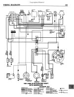
The voltage regulator on my 1965 40 hp Evinrude Lark VII selectric is missing. If the part is no longer available on Marineengine.com and I haven't found it elsewhere either. How can I determine the output voltage of the original part and use a newer part as a substitute? I don't see those properties in the wiring diagram(attached) that I found and I don't know how to work towards a solution. Any ideas?

Also, how can I bypass the external electronics and just run the motor on a stand? I am working my way through cleaning and lubricating along with the tune up guidelines detailed in my 1975 Clymer service manual, but it doesn't detail bypassing the electronics for starting it in my situation. Any help would be appreciated.

Thank you in advance for any wisdom and knowledge you can pass on to a fledgling boat restorer.


Attachments

  • Electrical_Selectric_Merged.jpg
    Electrical_Selectric_Merged.jpg
    550.5 KB · Views: 107
It used a Prestolite 10 Amp regulator. You won't find an automotive regulator that limits output to only 10 Amps. Allowing more than ten can burn up the generator. There was a Harley Davidson that used a similar regulator, but hey those are oldies too. Fortunately, the correct regulators show up on e-bay every now and then. There is one right now. Search for Evinrude regulator 383609.

You can start the motor by disconnecting one of the black wires coming from the magneto.
 
The motor will run without a voltage regulator, so you might want to hold off purchasing one till you know what you have.
 
Thank you for the quick responses. I have ordered the part on eBay and will continue working on the motor until it arrives. I'll check back in with an update in the future.
 
I'm back to working on this motor and am mystified by the electrical system. I have removed the starting solenoid (seen in electrical box photo), tested it by connecting 12V + and - to the small posts, and checking resistance at the two large terminals. The OHM reading showed 0.1 resistance at the two large terminals. Based on the YouTube video I had learned from, hearing the sound of the magnet activating inside the solenoid completing the circuit with a 0 resistance reading, this solenoid is working. However, when I wire it up to my setup as shown in these photos, nothing happens when I engage the ignition switch. I have verified that the white wire at the ignition switch reads 12.73V when I turn the key. The same white wire also reads 12.73V at the small terminal on the solenoid, but there is no sound of the magnet engaging and thus no current reaching the starter. What the heck am I missing!!??

Here are photos of my testing setup. I removed them from my 1965 Lyman Runabout so I could do woodwork and flounder with the electrical system separately. Any help would be appreciated.
Lyman_electrical_motor-testing_2.jpgLyman_electrical_motor-testing_1.jpg
 
Last edited:
Is there a safety switch on this motor ?-----And where did you purchase the solenoid ( part # ) for this set up.----And have done a procedure called ---" polarizing "----- the voltage regulator , generator ?
 
I'm back to working on this motor and am mystified by the electrical system. I have removed the starting solenoid (seen in electrical box photo), tested it by connecting 12V + and - to the small posts, and checking resistance at the two large terminals. The OHM reading showed 0.1 resistance at the two large terminals. Based on the YouTube video I had learned from, hearing the sound of the magnet activating inside the solenoid completing the circuit with a 0 resistance reading, this solenoid is working. However, when I wire it up to my setup as shown in these photos, nothing happens when I engage the ignition switch. I have verified that the white wire at the ignition switch reads 12.73V when I turn the key. The same white wire also reads 12.73V at the small terminal on the solenoid, but there is no sound of the magnet engaging and thus no current reaching the starter. What the heck am I missing!!??

Here are photos of my testing setup. I removed them from my 1965 Lyman Runabout so I could do woodwork and flounder with the electrical system separately. Any help would be appreciated.
View attachment 26510View attachment 26511

So..you have 12.7V at the small solenoid terminal. What do you have at the other small terminal? Should be 0V (grounded by the safety switch)? If it is showing the same 12V, the safety switch is not grounding it. You can also ground it by a jumper as a check.
 
So I'm not sure about the polarizing, but am willing to try that next if necessary, but here’s something I tried and had some positive results.

I re-tested the solenoid removed from the system, by running a wire to each small post directly from the positive and negative posts on the battery. This caused the magnet inside the solenoid to move, thus completing the circuit, and resistance through the large posts was 0.0. I replaced the solenoid into the electrical system, turned the key and got nothing. After verifying that 12.7V was getting from the ignition to the solenoid, I figured there is some sort of disconnect or grounding problem on the 2nd small terminal that goes to the motor. I decided to connect that terminal directly to the negative terminal of the battery using an alligator clip. When I turned the ignition, the motor fired up with strength and power.

Here is a labelled image of my motor and I believe my labelling to be correct. If it’s wrong, please tell me.

Cutoff Switch_Evinrude 40 hp_model 40562A3.jpg
Having traced the white wire from that terminal to the motor, it appears to connect at the cut-off switch. From there a blue wire is connected to what I think is the “safety switch” and 2 black wires leave the cut-off switch heading to the flywheel and the other returns to the ignition switch. Where along that wiring route should the 2nd post of the solenoid receive it’s “grounding?” Or, why is the solenoid working with a direct connect to the negative battery terminal, but not without?
 
As stated you found the safety switch.----If too much throttle is applied the motor will not crank.----Not sure which safety switch is on your motor.-----Those safety switches have only one wire to them and have an internal ground.----Yes some of those safety switches can be cleaned if ground is dirty.---Or adjusted to allow cranking.---Close-up picture of your safety switch ?------Easy fix here.
 
Safety switch close-up
DSC_4812_Safety_switch.JPGDSC_4811_Safety_switch.JPG

Cutoff switch close-up
forgot to reattach wires for the photo)
DSC_4815_Cutoff_switch.jpgDSC_4814_Cutoff_switch.jpg

I have not tried anything further, but I assume that removing the flywheel is my next step so that I can clean and tinker with the safety switch?

Should I also remove and clean the cutoff switch?

Lastly, for now, what is this part called? It appears to adjust leanness of fuel, but I thought that was done on the front of the carburetor by adjusting the idle. Can I clean it in place or should it be removed and cleaned more thoroughly?
Fuel_mix_20210330_3.jpgFuel_mix_20210330_2.jpg
 
That is a " bi-metalic spring "-----It re-acts to the air temperature coming from heat exchanger in the exhaust.-----Part of the choke set-up.-----That safety switch is easy to clean if internal ground is dirty.
 
I am trying to isolate the electrical issue and let me know if you agree with my assessment.

When I jump (shown below) from the white wire (upper right) of the cut-off switch , to the black wire (front center) of the cut-off switch, the ignition system works.

IMG_20210413_085305306.jpg

Four other scenarios I tried:
  1. Safety switch wire disconnected = got nothing.
  2. Safety switch wire disconnected + with jumper cable = ignition worked.
  3. Bypass cut-off switch by disconnecting all 4 wires (white, blue, blacks (x2)) and used the jumper cable to connect the wires as follows:

  • white + both blacks = ignition worked
  • white, blue + both blacks = ignition worked

I think, by process of elimination that the cutoff switch is my failed link in the circuit. I plan to remove it and see what's there but wanted to throw it out there for any feedback and wisdom you can offer.
 
The white wire that goes to the safety switch goes to GROUND if throttle is in idle / fast idle position.------Motor will not crank at full throttle..----So CLEAN the safety switch internal part or check the adjustment of it.----So simple to do.----I do not believe I can make it any clearer.
 
I'm planning to remove the safety switch and clean the ground tomorrow. Just to make sure I'm not missing something, I believe this will require the removal of the flywheel, since the removal screws are covered by the flywheel. Can I safely test the success of cleaning the ground before I put the flywheel back on? Also, are there any typical maintenance items I should do while I have the flywheel off?

Thanks again. I'm a total newbie at this.
 
You are good. I felt a bit foolish when I looked more closely and identified the bracket. After putting my “hammer away,” I removed the switch; cleaned it; did the same with the cut-off unit; put them all back together and low and behold...the engine fired up with the ignition!!! So gratifying.

Next up is getting her purring like a kitten. If you’re still willing to advise, I’m listening. I have a Klymer manual that I will use to troubleshoot and tune her up, but if you hear/see something that is obvious, please let me know. The increase and decrease in RPMs you’ll here is mostly happening on its own. I was moving the accelerator lever a bit, but it seemed to rise and fall quite out of sync with my movements.

Engine Running:
https://youtu.be/U9qqjsejnk8


Garage Setup:
https://youtu.be/D-Zx3vcGhws
 
Last edited:
Looked at the video for 5 seconds.-----Stop running this motor on muffs like that.-----The main water intake screen is behind the prop !----Looked again and motor is obviously running on 1 cylinder at first.----And it should fire up almost instantly .-----Remove flywheel and give the simple magneto some attention.----And make sure that the generator is working as when in gear there is constant 12 volts applied to electromagnets.
 
Last edited:
That motor is running on one cylinder most of the time. ESPECIALLY when you are revving it up like that. The vacuum cut-out switch kills the spark on one cylinder when you rev it up in neutral (that's what it is for). It is also "lean sneezing". I say you need to do a complete servicing, starting with a compression check (both cylinders and crankcase), then ignition service, carburetor, and link & sync. At least that is the approach I would take if somebody brought it to me.
 
Well------All I can say is that revving it up like that proves absolutely nothing !!-----May even destroy the motor.-----Answer these questions.-----Have you pulled the flywheel to inspect the coils ?---Does spark jump a gap of 1/4" or more on a test device ?-----Done a compression test ?----If so post the actual numbers.----Looked at pistons and rings via the bypass covers ?----Stop running it like that as it is easy to determine what is wrong.
 
Well------All I can say is that revving it up like that proves absolutely nothing !!-----May even destroy the motor.-----Answer these questions.-----Have you pulled the flywheel to inspect the coils ?---Does spark jump a gap of 1/4" or more on a test device ?-----Done a compression test ?----If so post the actual numbers.----Looked at pistons and rings via the bypass covers ?----Stop running it like that as it is easy to determine what is wrong.

Turns out to be even simpler, spark plug wire disconnected from coil for bottom cylinder. Pulling FW now to reattach.

thanks for the reply - hopefully this is all it needs

SB
 
Wires are held in place by clamps.----Have never seen those wires pull out of a coil.

I'm guessing incompetent PO :)
Looks like wire was replaced but not routed back correctly as wire was on other side of motor when i got it. Let's see if reattaching solves problems. It can't hurt. LOL
Just have to buy an impact wrench as damn flywheel nut is refusing to budge.

updates later

SB
 
90-sec video of motor running well Day 1 and poorly Day 2: https://youtu.be/NynpWorIdeY

Video is labelled every 10 seconds indicating various states: F, R, N, idle, fast, slow.

First Day, engine ran very well on 90 octane 100% non-ethanol gasoline, mixed 50:1 with 2-stroke Pennzoil rated for outboard motors.


Day 2, ran well first thing in the morning for about 20 minutes on smooth water. Fuel line apparently wasn't securely on fuel pump and came off stalling the motor abruptly. Connected the fuel line snuggly and ran the boat smoothly again.


Later that day, took the boat out and was zooming along at 90% throttle when engine stalled roughly sputtering. Struggled to start and then never ran smoothly again as seen in the last 45 seconds of this video. Fuel line was still snuggly connected. Not sure where to begin troubleshooting.


I say you have spark problems.------Are the coils , points , condensers and wires new, yes or no ?----The motor is running but it sounds awful ( painful ) to my ears !
 
No, not new. Is all of that replaceable with removal of flywheel?
I'm here near Muskegon, MI hopeful that I can find and replace all of that tomorrow. What do you figure the chances of finding those replacement parts in a small lake town are?
 
Back
Top